D7212G
Off-board Points
8.3.6POPIT Module Point Assignments
Seven switches on each D9127U/T POPIT (six on each D8127U/T POPIT) assign the module to a point number. POPIT switch settings are found in Point Assignment in the D7212G Program Record Sheet (P/N: 4998138542). See Figure 14.
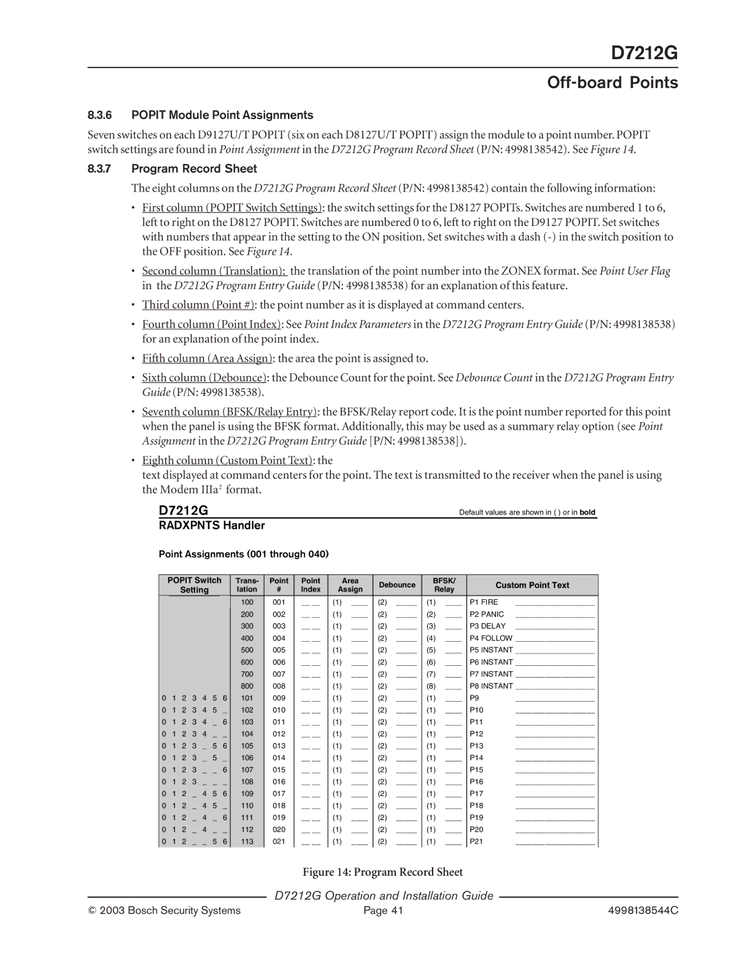
8.3.7Program Record Sheet
The eight columns on the D7212G Program Record Sheet (P/N: 4998138542) contain the following information:
•First column (POPIT Switch Settings): the switch settings for the D8127 POPITs. Switches are numbered 1 to 6, left to right on the D8127 POPIT. Switches are numbered 0 to 6, left to right on the D9127 POPIT. Set switches with numbers that appear in the setting to the ON position. Set switches with a dash
•Second column (Translation): the translation of the point number into the ZONEX format. See Point User Flag
in the D7212G Program Entry Guide (P/N: 4998138538) for an explanation of this feature.
•Third column (Point #): the point number as it is displayed at command centers.
•Fourth column (Point Index): See Point Index Parameters in the D7212G Program Entry Guide (P/N: 4998138538) for an explanation of the point index.
•Fifth column (Area Assign): the area the point is assigned to.
•Sixth column (Debounce): the Debounce Count for the point. See Debounce Count in the D7212G Program Entry
Guide (P/N: 4998138538).
•Seventh column (BFSK/Relay Entry): the BFSK/Relay report code. It is the point number reported for this point when the panel is using the BFSK format. Additionally, this may be used as a summary relay option (see Point Assignment in the D7212G Program Entry Guide [P/N: 4998138538]).
•Eighth column (Custom Point Text): the
text displayed at command centers for the point. The text is transmitted to the receiver when the panel is using the Modem IIIa2 format.
D7212G | Default values are shown in ( ) or in bold |
RADXPNTS Handler
Point Assignments (001 through 040)
POPIT Switch
Setting
|
|
|
|
|
|
|
|
|
|
|
|
|
|
|
|
|
|
|
|
|
|
|
|
|
|
|
|
|
|
|
|
|
|
|
|
|
|
|
|
|
|
|
|
|
|
|
|
|
0 | 1 | 2 | 3 | 4 | 5 | 6 |
0 | 1 | 2 | 3 | 4 | 5 | _ |
0 | 1 | 2 | 3 | 4 | _ | 6 |
0 | 1 | 2 | 3 | 4 | _ | _ |
0 | 1 | 2 | 3 | _ | 5 | 6 |
0 | 1 | 2 | 3 | _ | 5 | _ |
0 | 1 | 2 | 3 | _ | _ | 6 |
0 | 1 | 2 | 3 | _ | _ | _ |
0 | 1 | 2 | _ | 4 | 5 | 6 |
0 | 1 | 2 | _ | 4 | 5 | _ |
0 | 1 | 2 | _ | 4 | _ | 6 |
0 | 1 | 2 | _ | 4 | _ | _ |
0 | 1 | 2 | _ | _ | 5 | 6 |
|
|
|
|
|
|
|
Trans- | Point | Point |
| Area | Debounce | BFSK/ |
| Custom Point Text | |||
lation | # | Index | Assign | Relay |
| ||||||
|
|
|
|
| |||||||
100 | 001 | __ __ | (1) | ____ | (2) | _____ | (1) | ____ | P1 | FIRE | ___________________ |
200 | 002 | __ __ | (1) | ____ | (2) | _____ | (2) | ____ | P2 | PANIC | ___________________ |
300 | 003 | __ __ | (1) | ____ | (2) | _____ | (3) | ____ | P3 | DELAY | ___________________ |
400 | 004 | __ __ | (1) | ____ | (2) | _____ | (4) | ____ | P4 | FOLLOW ___________________ | |
500 | 005 | __ __ | (1) | ____ | (2) | _____ | (5) | ____ | P5 | INSTANT ___________________ | |
600 | 006 | __ __ | (1) | ____ | (2) | _____ | (6) | ____ | P6 | INSTANT ___________________ | |
700 | 007 | __ __ | (1) | ____ | (2) | _____ | (7) | ____ | P7 | INSTANT ___________________ | |
800 | 008 | __ __ | (1) | ____ | (2) | _____ | (8) | ____ | P8 | INSTANT ___________________ | |
101 | 009 | __ __ | (1) | ____ | (2) | _____ | (1) | ____ | P9 |
| ___________________ |
102 | 010 | __ __ | (1) | ____ | (2) | _____ | (1) | ____ | P10 | ___________________ | |
103 | 011 | __ __ | (1) | ____ | (2) | _____ | (1) | ____ | P11 | ___________________ | |
104 | 012 | __ __ | (1) | ____ | (2) | _____ | (1) | ____ | P12 | ___________________ | |
105 | 013 | __ __ | (1) | ____ | (2) | _____ | (1) | ____ | P13 | ___________________ | |
106 | 014 | __ __ | (1) | ____ | (2) | _____ | (1) | ____ | P14 | ___________________ | |
107 | 015 | __ __ | (1) | ____ | (2) | _____ | (1) | ____ | P15 | ___________________ | |
108 | 016 | __ __ | (1) | ____ | (2) | _____ | (1) | ____ | P16 | ___________________ | |
109 | 017 | __ __ | (1) | ____ | (2) | _____ | (1) | ____ | P17 | ___________________ | |
110 | 018 | __ __ | (1) | ____ | (2) | _____ | (1) | ____ | P18 | ___________________ | |
111 | 019 | __ __ | (1) | ____ | (2) | _____ | (1) | ____ | P19 | ___________________ | |
112 | 020 | __ __ | (1) | ____ | (2) | _____ | (1) | ____ | P20 | ___________________ | |
113 | 021 | __ __ | (1) | ____ | (2) | _____ | (1) | ____ | P21 | ___________________ | |
|
|
|
|
|
|
|
|
|
|
|
|
Figure 14: Program Record Sheet
D7212G Operation and Installation Guide
© 2003 Bosch Security Systems | Page 41 | 4998138544C |