D7212G
Off-board Points
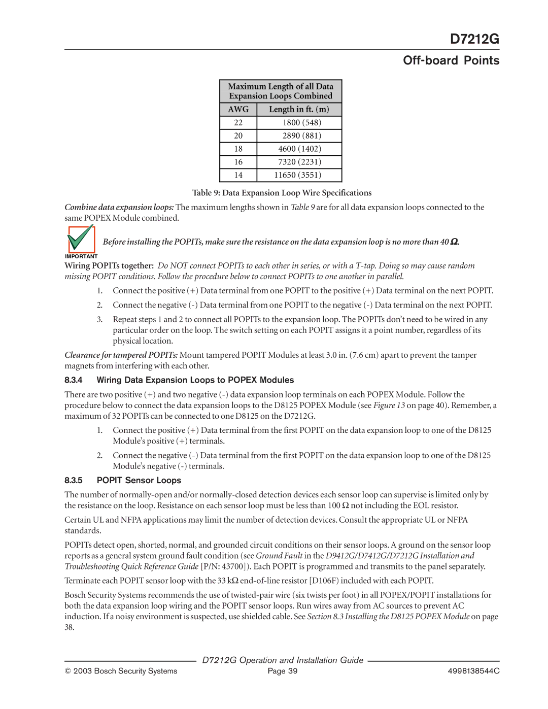
Maximum Length of all Data
Expansion Loops Combined
AWG
Length in ft. (m)
22 | 1800 (548) | |
|
| |
20 | 2890 (881) | |
|
|
|
18 | 4600 | (1402) |
|
|
|
16 | 7320 | (2231) |
|
|
|
14 | 11650 | (3551) |
|
|
|
Table 9: Data Expansion Loop Wire Specifications
Combine data expansion loops: The maximum lengths shown in Table 9 are for all data expansion loops connected to the same POPEX Module combined.
Before installing the POPITs, make sure the resistance on the data expansion loop is no more than 40 Ω.
IMPORTANT
Wiring POPITs together: Do NOT connect POPITs to each other in series, or with a
1.Connect the positive (+) Data terminal from one POPIT to the positive (+) Data terminal on the next POPIT.
2.Connect the negative
3.Repeat steps 1 and 2 to connect all POPITs to the expansion loop. The POPITs don’t need to be wired in any particular order on the loop. The switch setting on each POPIT assigns it a point number, regardless of its physical location.
Clearance for tampered POPITs: Mount tampered POPIT Modules at least 3.0 in. (7.6 cm) apart to prevent the tamper magnets from interfering with each other.
8.3.4Wiring Data Expansion Loops to POPEX Modules
There are two positive (+) and two negative
1.Connect the positive (+) Data terminal from the first POPIT on the data expansion loop to one of the D8125 Module’s positive (+) terminals.
2.Connect the negative
8.3.5POPIT Sensor Loops
The number of
Certain UL and NFPA applications may limit the number of detection devices. Consult the appropriate UL or NFPA standards.
POPITs detect open, shorted, normal, and grounded circuit conditions on their sensor loops. A ground on the sensor loop reports as a general system ground fault condition (see Ground Fault in the D9412G/D7412G/D7212G Installation and Troubleshooting Quick Reference Guide [P/N: 43700]). Each POPIT is programmed and transmits to the panel separately.
Terminate each POPIT sensor loop with the 33 kΩ
Bosch Security Systems recommends the use of
D7212G Operation and Installation Guide
© 2003 Bosch Security Systems | Page 39 | 4998138544C |