D7212G
Introduction
1.0Introduction
This guide addresses the operation and installation of the D7212G Control/Communicator only and should not be used in conjunction with the D9412G, D7412G, D9412, D9112, D9112B1, D7412, D7212 or D7212B1 Panels.
Throughout this guide, unless expressly stated, the words “panel” and “control/communicator” refer to the D7212G.
Section 2.1 9000G Series Panel Differences on page 13 provides an overview of the differences between the D9412G, D7412G, and D7212G panels.
1.1Guide Organization
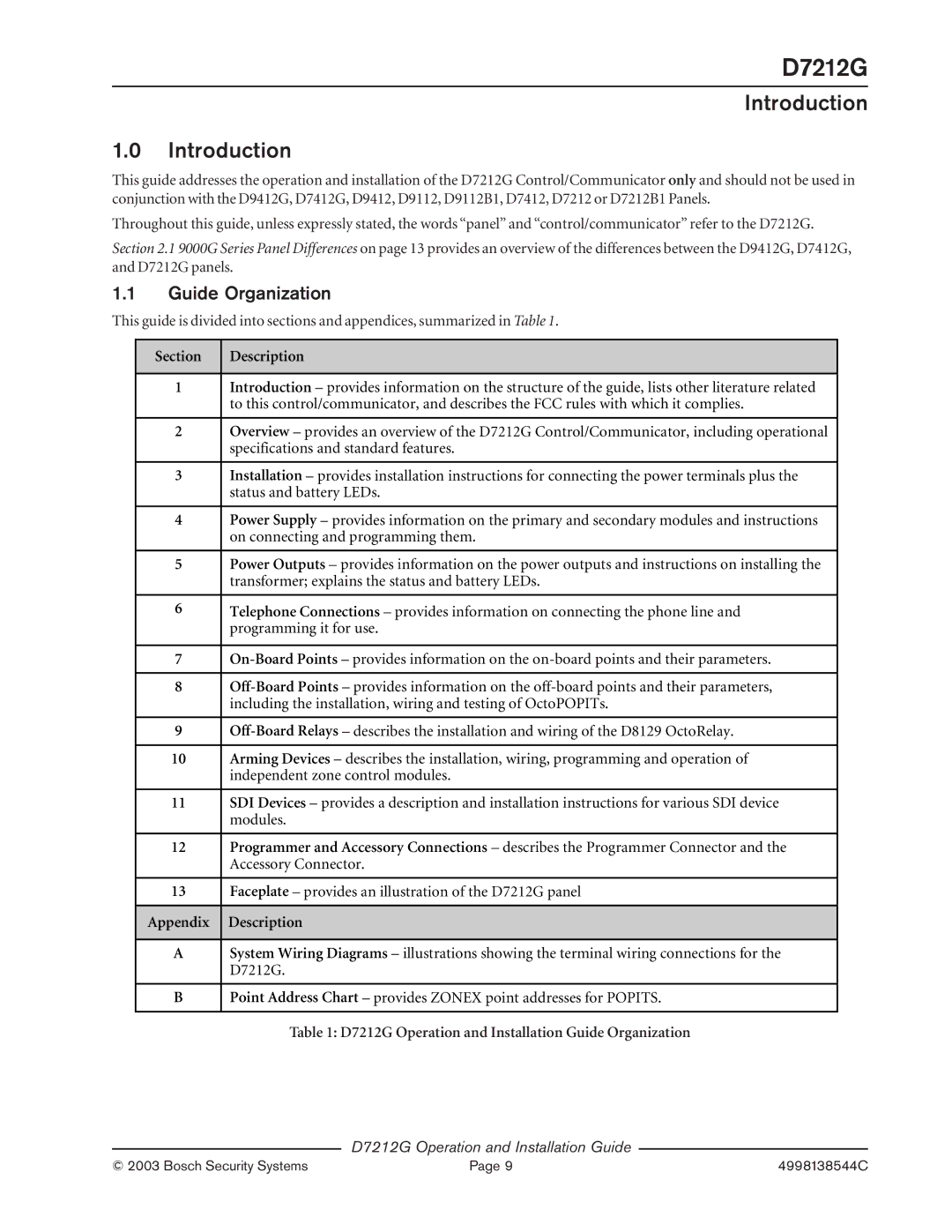
This guide is divided into sections and appendices, summarized in Table 1.
Section | Description |
|
|
1 | Introduction – provides information on the structure of the guide, lists other literature related |
| to this control/communicator, and describes the FCC rules with which it complies. |
|
|
2 | Overview – provides an overview of the D7212G Control/Communicator, including operational |
| specifications and standard features. |
|
|
3 | Installation – provides installation instructions for connecting the power terminals plus the |
| status and battery LEDs. |
|
|
4 | Power Supply – provides information on the primary and secondary modules and instructions |
| on connecting and programming them. |
|
|
5 | Power Outputs – provides information on the power outputs and instructions on installing the |
| transformer; explains the status and battery LEDs. |
|
|
6 | Telephone Connections – provides information on connecting the phone line and |
| programming it for use. |
|
|
7 | |
|
|
8 | |
| including the installation, wiring and testing of OctoPOPITs. |
|
|
9 | |
|
|
10 | Arming Devices – describes the installation, wiring, programming and operation of |
| independent zone control modules. |
|
|
11 | SDI Devices – provides a description and installation instructions for various SDI device |
| modules. |
|
|
12 | Programmer and Accessory Connections – describes the Programmer Connector and the |
| Accessory Connector. |
|
|
13 | Faceplate – provides an illustration of the D7212G panel |
|
|
Appendix | Description |
|
|
A | System Wiring Diagrams – illustrations showing the terminal wiring connections for the |
| D7212G. |
|
|
B | Point Address Chart – provides ZONEX point addresses for POPITS. |
|
|
Table 1: D7212G Operation and Installation Guide Organization
D7212G Operation and Installation Guide
© 2003 Bosch Security Systems | Page 9 | 4998138544C |