D7212G
Overview
2.2Specifications
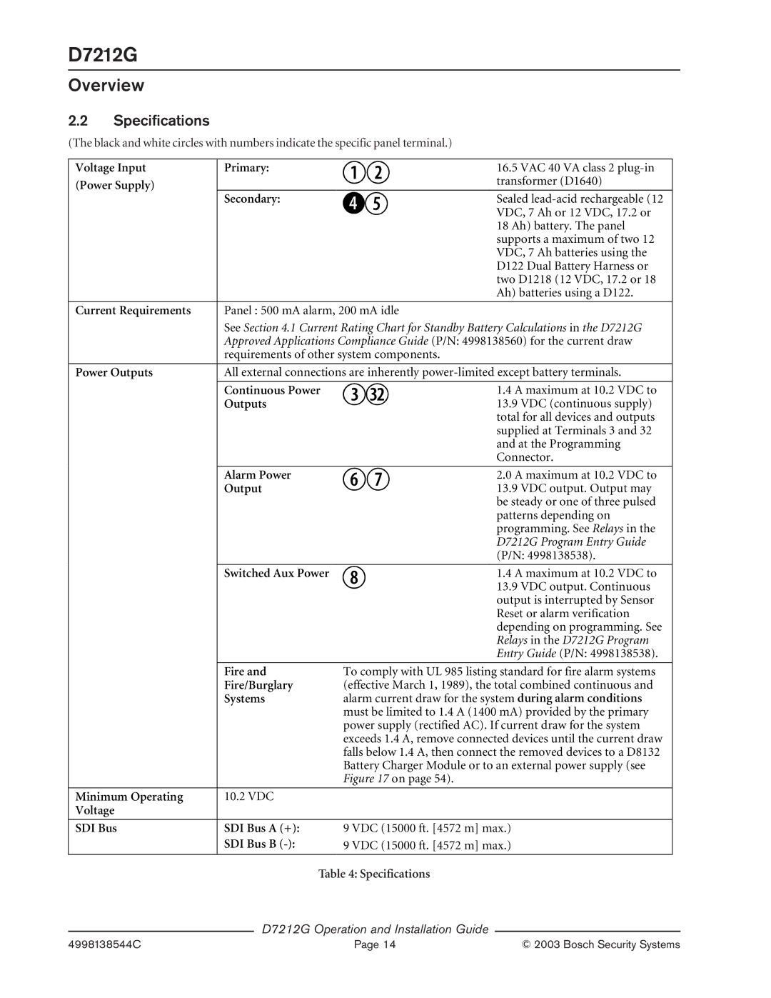
(The black and white circles with numbers indicate the specific panel terminal.)
Voltage Input | Primary: |
| 16.5 VAC 40 VA class 2 |
(Power Supply) |
|
| transformer (D1640) |
|
|
| |
| Secondary: |
| Sealed |
|
|
| VDC, 7 Ah or 12 VDC, 17.2 or |
|
|
| 18 Ah) battery. The panel |
|
|
| supports a maximum of two 12 |
|
|
| VDC, 7 Ah batteries using the |
|
|
| D122 Dual Battery Harness or |
|
|
| two D1218 (12 VDC, 17.2 or 18 |
|
|
| Ah) batteries using a D122. |
|
|
| |
Current Requirements | Panel : 500 mA alarm, 200 mA idle | ||
| See Section 4.1 Current Rating Chart for Standby Battery Calculations in the D7212G | ||
| Approved Applications Compliance Guide (P/N: 4998138560) for the current draw | ||
| requirements of other system components. | ||
|
|
| |
Power Outputs | All external connections are inherently | ||
|
|
|
|
| Continuous Power |
| 1.4 A maximum at 10.2 VDC to |
| Outputs |
| 13.9 VDC (continuous supply) |
|
|
| total for all devices and outputs |
|
|
| supplied at Terminals 3 and 32 |
|
|
| and at the Programming |
|
|
| Connector. |
|
|
|
|
| Alarm Power |
| 2.0 A maximum at 10.2 VDC to |
| Output |
| 13.9 VDC output. Output may |
|
|
| be steady or one of three pulsed |
|
|
| patterns depending on |
|
|
| programming. See Relays in the |
|
|
| D7212G Program Entry Guide |
|
|
| (P/N: 4998138538). |
|
|
|
|
| Switched Aux Power |
| 1.4 A maximum at 10.2 VDC to |
|
|
| 13.9 VDC output. Continuous |
|
|
| output is interrupted by Sensor |
|
|
| Reset or alarm verification |
|
|
| depending on programming. See |
|
|
| Relays in the D7212G Program |
|
|
| Entry Guide (P/N: 4998138538). |
|
|
|
|
| Fire and | To comply with UL 985 listing standard for fire alarm systems | |
| Fire/Burglary | (effective March 1, 1989), the total combined continuous and | |
| Systems | alarm current draw for the system during alarm conditions | |
|
| must be limited to 1.4 A (1400 mA) provided by the primary | |
|
| power supply (rectified AC). If current draw for the system | |
|
| exceeds 1.4 A, remove connected devices until the current draw | |
|
| falls below 1.4 A, then connect the removed devices to a D8132 | |
|
| Battery Charger Module or to an external power supply (see | |
|
| Figure 17 on page 54). | |
|
|
|
|
Minimum Operating | 10.2 VDC |
|
|
Voltage |
|
|
|
|
|
|
|
SDI Bus | SDI Bus A (+): | 9 VDC (15000 ft. [4572 m] max.) | |
| SDI Bus B | 9 VDC (15000 ft. [4572 m] max.) | |
|
|
|
|
Table 4: Specifications
D7212G Operation and Installation Guide
4998138544C | Page 14 | © 2003 Bosch Security Systems |