D7212G
On-board Points
7.0On-board Points
7.1Description Terminals 


The panel provides eight on-board points. Each point functions independently and does not interfere with the operation of the others. The panel monitors the sensor loops for normal, shorted, or open conditions between an input terminal (11, 13, 14, 16, 17, 19, 20, or 22) and any of the point common terminals (12, 15, 18, and 21). Programming for the point determines how the panel responds to those conditions. See the D7212G Program Entry Guide (P/N: 4998138538) for point programming options. The panel also monitors the sensor loops for ground fault conditions if S4 is latched (ground fault detect enabled).
7.2Point Sensor Loops
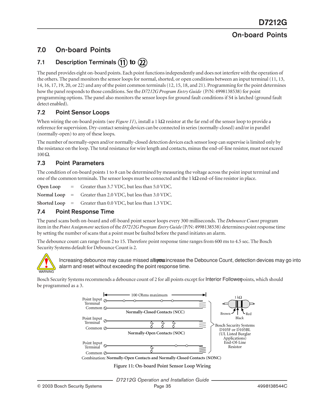
When wiring the on-board points (see Figure 11), install a 1 kΩ resistor at the far end of the sensor loop to provide a reference for supervision. Dry-contact sensing devices can be connected in series (normally-closed) and/or in parallel (normally-open) to any of these loops.
The number of normally-open and/or normally-closed detection devices each sensor loop can supervise is limited only by the resistance on the loop. The total resistance for wire length and contacts, minus the end-of-line resistor, must not exceed
100Ω.
7.3Point Parameters
The condition of on-board points 1 to 8 can be determined by measuring the voltage across the point input terminal and one of the common terminals. The sensor loops must be connected and the 1 kΩ end-of-line resistor in place.
Open Loop | = | Greater than 3.7 VDC, but less than 5.0 VDC. |
Normal Loop | = | Greater than 2.0 VDC, but less than 3.0 VDC. |
Shorted Loop | = | Greater than 0.0 VDC, but less than 1.3 VDC. |
7.4Point Response Time
The panel scans both on-board and off-board point sensor loops every 300 milliseconds. The Debounce Count program item in the Point Assignment section of the D7212G Program Entry Guide (P/N: 4998138538) determines point response time by setting the number of scans that a point must be faulted before the panel initiates an alarm.
The debounce count can range from 2 to 15. Therefore point response time ranges from 600 ms to 4.5 sec. The Bosch Security Systems default for Debounce Count is 2.
Increasing debounce may cause missed alarms: If you increase the Debounce Count, detection devices may go into alarm and reset without exceeding the point response time.
WARNING
Bosch Security Systems recommends a debounce count of 2 for all points except for Interior Follower points, which should be programmed as a 3.
| 100 Ohms maximum | 1 kΩ | |
| Point Input | |
| | |
| Terminal | | |
| Common | | |
| Normally-Closed Contacts (NCC) | Brown | Red |
| |
| Point Input | Black | |
| Terminal | Bosch Security Systems |
| Common |
| D105F or D105BL |
| Normally-Open Contacts (NOC) |
| (UL Listed Burglar |
| | Applications) |
| Point Input | End-Of-Line |
| Terminal | Resistor | |
Common 
Combination: Normally-Open Contacts and Normally-Closed Contacts (NONC)
Figure 11: On-board Point Sensor Loop Wiring
D7212G Operation and Installation Guide