D7212G
SDI Devices
11.4SDI Address 80
SDI Address 80 is available on the D7212G Panel and allows
11.4.1D9133 Serial Interface Module
The Bosch Security Systems D9133 Serial Interface Module is a
The D9133 can be installed up to 1000 ft. (305 m) away from the panel using 18 AWG wire. The D9133 is not UL Listed.
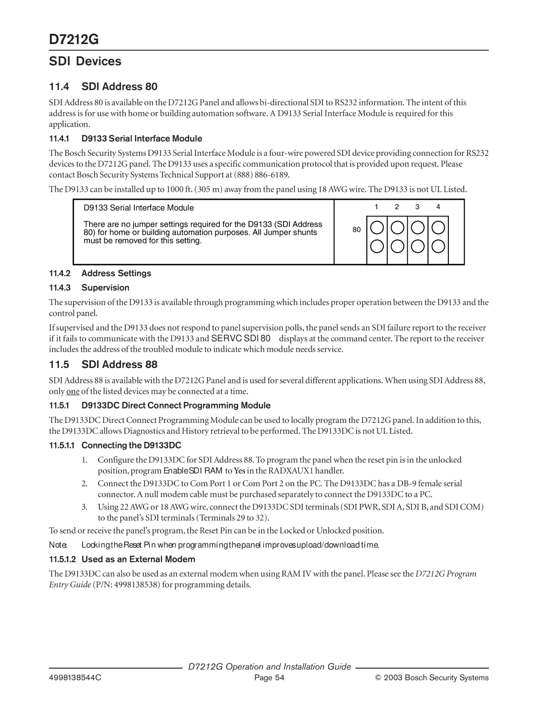
D9133 Serial Interface Module
There are no jumper settings required for the D9133 (SDI Address
80)for home or building automation purposes. All Jumper shunts must be removed for this setting.
1 | 2 | 3 | 4 |
80
11.4.2Address Settings
11.4.3Supervision
The supervision of the D9133 is available through programming which includes proper operation between the D9133 and the control panel.
If supervised and the D9133 does not respond to panel supervision polls, the panel sends an SDI failure report to the receiver if it fails to communicate with the D9133 and SERVC SDI 80 displays at the command center. The report to the receiver includes the address of the troubled module to indicate which module needs service.
11.5SDI Address 88
SDI Address 88 is available with the D7212G Panel and is used for several different applications. When using SDI Address 88, only one of the listed devices may be connected at a time.
11.5.1D9133DC Direct Connect Programming Module
The D9133DC Direct Connect Programming Module can be used to locally program the D7212G panel. In addition to this, the D9133DC allows Diagnostics and History retrieval to be performed. The D9133DC is not UL Listed.
11.5.1.1Connecting the D9133DC
1.Configure the D9133DC for SDI Address 88. To program the panel when the reset pin is in the unlocked position, program Enable SDI RAM to Yes in the RADXAUX1 handler.
2.Connect the D9133DC to Com Port 1 or Com Port 2 on the PC. The D9133DC has a
3.Using 22 AWG or 18 AWG wire, connect the D9133DC SDI terminals (SDI PWR, SDI A, SDI B, and SDI COM) to the panel’s SDI terminals (Terminals 29 to 32).
To send or receive the panel’s program, the Reset Pin can be in the Locked or Unlocked position.
Note: Locking the Reset Pin when programming the panel improves upload/download time.
11.5.1.2 Used as an External Modem
The D9133DC can also be used as an external modem when using RAM IV with the panel. Please see the D7212G Program Entry Guide (P/N: 4998138538) for programming details.
D7212G Operation and Installation Guide
4998138544C | Page 54 | © 2003 Bosch Security Systems |