2 Installing and replacing a switch module
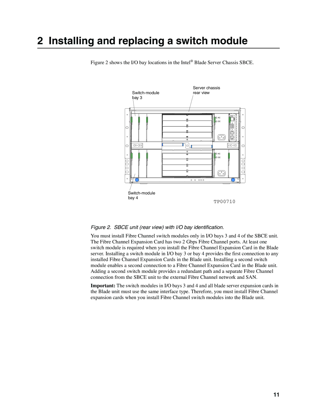
Figure 2 shows the I/O bay locations in the Intel® Blade Server Chassis SBCE.
Server chassis
AC
DC
AC
DC
TP00710
Figure 2. SBCE unit (rear view) with I/O bay identification.
You must install Fibre Channel switch modules only in I/O bays 3 and 4 of the SBCE unit. The Fibre Channel Expansion Card has two 2 Gbps Fibre Channel ports. At least one switch module is required when you install the Fibre Channel Expansion Card in the Blade server. Installing a switch module in I/O bay 3 or bay 4 provides the first connection to any installed Fibre Channel Expansion Cards in the Blade unit. Installing a second switch module enables a second connection to a Fibre Channel Expansion Card in the Blade unit. Adding a second switch module provides a redundant path and a separate Fibre Channel connection from the SBCE unit to the external Fibre Channel network and SAN.
Important: The switch modules in I/O bays 3 and 4 and all blade server expansion cards in the Blade unit must use the same interface type. Therefore, you must install Fibre Channel expansion cards when you install Fibre Channel switch modules into the Blade unit.
11
