Class 1 Laser Product
Laser Klasse 1
Laser Klass 1
Luokan 1 Laserlaite
`
Appareil A Laser de Classe 1
Statement 8:
xxCAUTION:
Never remove the cover on a power supply or any part that has the following label attached.
xxCAUTION:
Hazardous voltage, current, and energy levels are present inside any component that has this label attached. There are no serviceable parts inside these components. If you suspect a problem with one of these parts, contact a service technician.
Complete the following steps to install a switch module:
1.Review the information in “Safety and regulatory information” on page v and “Installation guidelines” on page 12 through “Handling
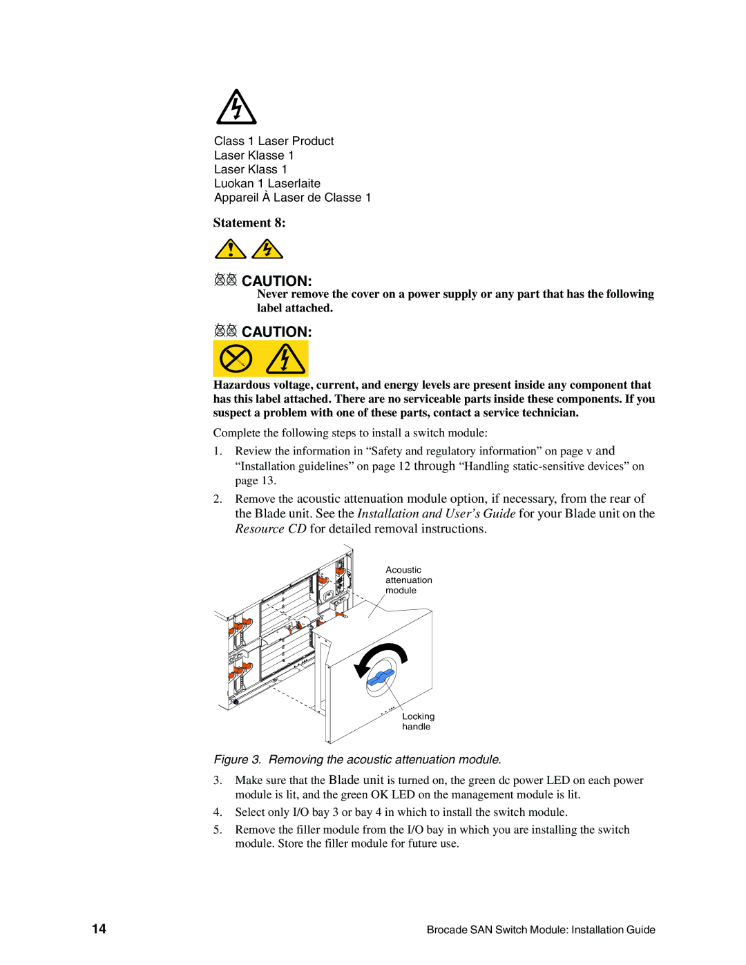
2.Remove the acoustic attenuation module option, if necessary, from the rear of the Blade unit. See the Installation and User’s Guide for your Blade unit on the Resource CD for detailed removal instructions.
Acoustic attenuation module
Locking handle
Figure 3. Removing the acoustic attenuation module.
3.Make sure that the Blade unit is turned on, the green dc power LED on each power module is lit, and the green OK LED on the management module is lit.
4.Select only I/O bay 3 or bay 4 in which to install the switch module.
5.Remove the filler module from the I/O bay in which you are installing the switch module. Store the filler module for future use.
14 | Brocade SAN Switch Module: Installation Guide |