OK !
OK LED (green) |
|
| Fault (system error) |
| LED (amber) |
Port speed LED | Port diagnostics LED |
2G RXTX !
0
Port status LED
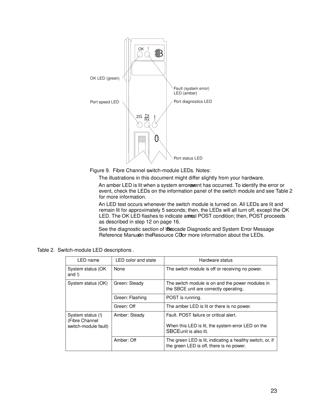
Figure 9. Fibre Channel switch-module LEDs. Notes:
•The illustrations in this document might differ slightly from your hardware.
•An amber LED is lit when a system error or event has occurred. To identify the error or event, check the LEDs on the information panel of the switch module and see Table 2 for more information.
•An LED test occurs whenever the switch module is turned on. All LEDs are lit and remain lit for approximately 5 seconds; then, the LEDs will all turn off, except the OK LED. The OK LED flashes to indicate a normal POST condition; then, POST proceeds as described in step 12 on page 16.
•See the diagnostic section of the Brocade Diagnostic and System Error Message Reference Manual on the Resource CD for more information about the LEDs.
Table 2. Switch-module LED descriptions .
LED name | LED color and state | Hardware status |
|
|
|
System status (OK | None | The switch module is off or receiving no power. |
and !) |
|
|
|
|
|
System status (OK) | Green: Steady | The switch module is on and the power modules in |
|
| the SBCE unit are correctly operating. |
|
|
|
| Green: Flashing | POST is running. |
|
|
|
| Green: Off | The amber LED is lit or there is no power. |
|
|
|
System status (!) | Amber: Steady | Fault. POST failure or critical alert. |
(Fibre Channel |
| When this LED is lit, the |
| ||
|
| SBCE unit is also lit. |
|
|
|
| Amber: Off | The green LED is lit, indicating a healthy switch, or, if |
|
| the green LED is off, there is no power. |
|
|
|
23
