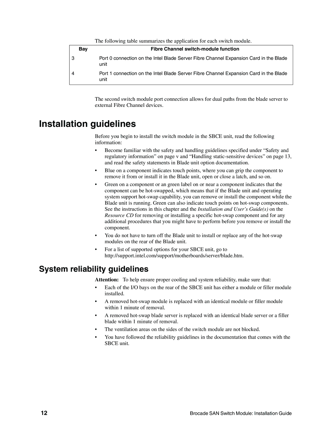
The following table summarizes the application for each switch module.
Bay | Fibre Channel |
3Port 0 connection on the Intel Blade Server Fibre Channel Expansion Card in the Blade unit
4Port 1 connection on the Intel Blade Server Fibre Channel Expansion Card in the Blade unit
The second switch module port connection allows for dual paths from the blade server to external Fibre Channel devices.
Installation guidelines
Before you begin to install the switch module in the SBCE unit, read the following information:
•Become familiar with the safety and handling guidelines specified under “Safety and regulatory information” on page v and “Handling
•Blue on a component indicates touch points, where you can grip the component to remove it from or install it in the Blade unit, open or close a latch, and so on.
•Green on a component or an green label on or near a component indicates that the component can be
•You do not have to turn off the Blade unit to install or replace any of the
•For a list of supported options for your SBCE unit, go to http://support.intel.com/support/motherboards/server/blade.htm.
System reliability guidelines
Attention: To help ensure proper cooling and system reliability, make sure that:
•Each of the I/O bays on the rear of the SBCE unit has either a module or filler module installed.
•A removed
•A removed
•The ventilation areas on the sides of the switch module are not blocked.
•You have followed the reliability guidelines in the documentation that comes with the SBCE unit.
12 | Brocade SAN Switch Module: Installation Guide |