6.If you have not already done so, touch the
7.Remove the switch module from its
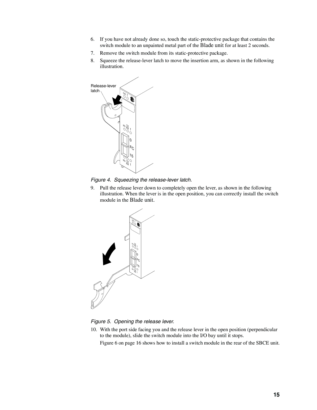
8.Squeeze the
OK
2G
!
TX RX
!
0 FC 15
2G TX RX
!
Figure 4. Squeezing the release-lever latch.
9.Pull the release lever down to completely open the lever, as shown in the following illustration. When the lever is in the open position, you can correctly install the switch module in the Blade unit.
OK
2G
!
TX RX
!
0 FC 15
2G TX RX
!
Figure 5. Opening the release lever.
10.With the port side facing you and the release lever in the open position (perpendicular to the module), slide the switch module into the I/O bay until it stops.
Figure 6 on page 16 shows how to install a switch module in the rear of the SBCE unit.
15
