4.Remove any SFP modules from the
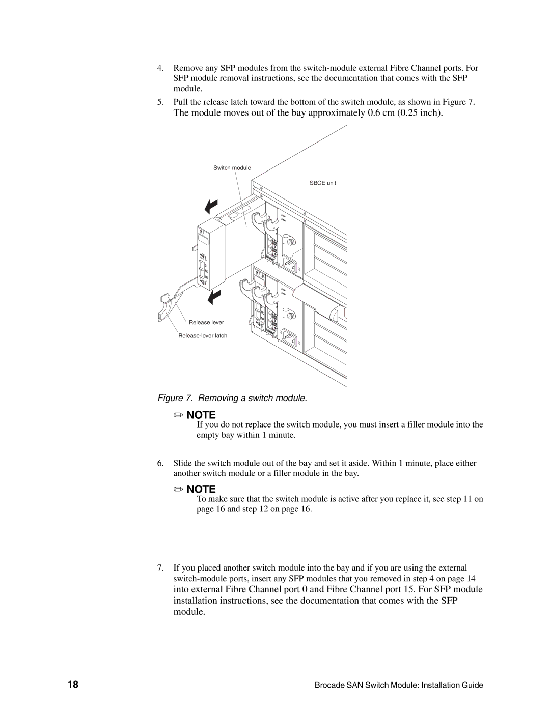
5.Pull the release latch toward the bottom of the switch module, as shown in Figure 7. The module moves out of the bay approximately 0.6 cm (0.25 inch).
Switch module
SBCE unit
O |
|
K! |
|
2G TX |
|
RX | ! |
| 0 |
| F |
| C |
| 15 |
2 |
|
G TX | ! |
RX |
Release lever
| O |
|
|
|
| K! |
|
|
|
|
| LI |
| |
|
|
| NK | |
|
| T | 1 |
|
|
| X/R | X | |
|
| LI | ||
|
|
| NK | |
|
| T | 2 |
|
|
| X/R | X | |
|
| LI | ||
|
|
| NK | |
|
| T | 3 |
|
|
| X/R | X | |
|
| LI | ||
|
|
| NK | |
|
|
| 4 |
|
| 00 | TX/ |
| |
| 055 |
| RX | |
| D89 |
|
| |
|
| A1 |
| |
|
|
| 44 | |
O |
|
|
|
|
K! |
|
|
|
|
| O |
|
|
|
| K! |
|
|
|
2G TX |
|
|
|
|
RX | ! |
|
|
|
|
| LI |
| |
|
|
| NK | |
| 0 | T | 1 |
|
|
| X/R | X | |
|
| LI | ||
| F |
| NK | |
|
| 2 |
| |
| C | T |
| |
| 15 | X/R | X | |
| LI | |||
|
| NK | ||
2 |
| T | 3 |
|
G TX |
| X/ |
| |
RX | ! |
| RX | |
LI |
| |||
|
|
| NK | |
|
|
| 4 |
|
| 00 | TX/ |
| |
| 055 |
| RX | |
| D89 |
|
| |
|
| A1 |
| |
|
|
| 44 | |
AC DC
AC DC
Figure 7. Removing a switch module.
✏NOTE
If you do not replace the switch module, you must insert a filler module into the empty bay within 1 minute.
6.Slide the switch module out of the bay and set it aside. Within 1 minute, place either another switch module or a filler module in the bay.
✏NOTE
To make sure that the switch module is active after you replace it, see step 11 on page 16 and step 12 on page 16.
7.If you placed another switch module into the bay and if you are using the external
18 | Brocade SAN Switch Module: Installation Guide |