—21—


BLOWER OFF DELAY


(WHEN USED)


TO 115VAC FIELD DISCONNECT


SCHEMATIC DIAGRAM


PCB


PRS


LGPS


(NATURAL GAS & PROPANE)


JUMPER SELECT


L1


L2


NOTE #2


GND


EQUIPMENT GROUND


PRINTED


J2

90

120


ORN


SPARE-2


MED LO


ILK


LO


CAP-1


CIRCIUT

G


150


NOTE #11


HEAT


MED HI


Com


YEL


L1


HI/LO


L2


180


SPARE-1


HI


24V


BLU


BLU


OL

START


BOARD

W


J1


M

GV


BLWR


COOL NOTE #10


EAC-2


ORN


LS


FRS


C


COM


Y


TEST/TWIN


RED

RED


BLWM


R


HUM


GRN/YEL


EAC-1


HSIR


FU1


RED


NOTE #3


NOTE #6


GRN/YEL


IDR


1


1

HSI


101198


IDM


LED 1

RED


TRAN


AUX


SEC-2


SEC-1


WHT


PL2

2

PL3

2


OL


BLU


BLK


PR1

115VAC


M


RED


EAC-2

L2

7

WHT


WHT


TRAN


NOTE#8


432 5 6

RED


WHT


NEUTRAL


PL4


2

CAP - 2


YEL


GRN/YEL


CAP -2


24VAC


1


GRN/YEL


BRN

BRN


TEST/TWIN


PL4

3


BLW


1

WHT


3


WHT


AUX


F U 1 NOTE #6


PL1


FSE


M


GRN/YEL


PL2


2


IDM


PRINTED


COOL


L1


PL3


OL


SEC-1


SEC-2


FRS

LS


1


6


BHT/CLR

BLWR


BLK


2

1


WHT


SPARE 1


SPARE 2

EAC-1


BLK


WHT

2

HSI


CIRCIUT


LGPS

(WHEN USED)


HEAT


BLK


8


BLK

1


R


PR1


BOARD

W


2


WHT

BLK (HI)


WHT

(COM)


WHT


HUM


PL1


NOTE #11


(COM)


BLK


PRS


BLWM


FUSED OR CIRCUIT BREAKER


GRN/YEL


YEL


JB


DISCONNECT SWITCH (WHEN REQ’D)


NOTE #2


(MED HI)


BRN


OL


4


WHT


WHT


NEUTRAL


FU2


NOTE #10


START

CAP -1


GVR-1


10


GV


BLK


L1


M


RED (LO)


BLK


BLU


ILK


CPU


BRN


GND


Y


5


C


(MED LO)


NOTE #3

L

BHT/CLR

BLOWER MOTOR SPEED CHANGE RELAY, SPDT


OL

AUTO-RESET INTERNAL MOTOR OVERLOAD


G


1


TEMPERATURE SWITCH (N.C.)


E BLWR


BLOWER MOTOR RELAY, SPST-(N.O.)


PCB

PRINTED CIRCUIT BOARD CONTROL


9


FSE


G

BLWM


BLOWER MOTOR, PERMANENT-SPLIT-CAPACITOR


PL1

11-CIRCUIT PCB CONNECTOR


CAP 1,2

CAPACITOR


E CPU


MICROPROCESSOR AND CIRCUITRY


PL2

2-CIRCUIT CONNECTOR


COM


7


N EAC-1


ELECTRONIC AIR CLEANER CONNECTION (115 VAC 1.0 AMP MAX.)

PL3

2-CIRCUIT HSI, CONNECTOR


PCB


3


PL4

3-CIRCUIT IDM EXTENSION CONNECTOR


24V


D

EAC-2


ELECTRONIC AIR CLEANER CONNECTION (COMMON)


NOTE #5


PRS

PRESSURE SWITCH, SPST-(N.O.)


11


FRS


FLAME ROLLOUT SW. -MANUAL RESET, SPST-(N.C.)


NOTES:


FSE


FLAME-PROVING ELECTRODE


TEST/TWIN


COMPONENT TEST & TWIN TERMINAL


FU 1


FUSE, 3 AMP, AUTOMOTIVE BLADE TYPE, FACTORY INSTALLED


TRAN

TRANSFORMER-115VAC/24VAC


1.

If any of the original equipment wire is replaced use wire rated for 105°C.


FU 2


FUSE OR CIRCUIT BREAKER CURRENT INTERRUPT DEVICE


JUNCTION


2.

Use only copper wire between the disconnect switch and the furnace junction box (JB).


(FIELD INSTALLED & SUPPLIED)


UNMARKED TERMINAL


3.

This wire must be connected to furnace sheet metal for control to prove flame.


GND


EQUIPMENT GROUND


4.

Symbols are electrical representation only.


GV


GAS VALVE-REDUNDANT


PCB CONTROL TERMINAL


5.

Solid lines inside PCB are printed circuit board conductors and are not included in legend.


GVR 1, 2

GAS VALVE RELAY, DPST-(N.O.)


FACTORY WIRING (115VAC)


6.

Replace only with a 3 amp fuse.


HSI


HOT SURFACE IGNITER (115 VAC)


FACTORY WIRING (24VAC)


7.

Inducer (IDM) and blower (BLWM) motors contain internal auto-reset thermal overload switches (OL).


HSIR


HOT SURFACE IGNITER RELAY, SPST-(N.O.)


8.

Neutral connections are interchangeable within the NEUTRAL connector block.


HUM


24VAC HUMIDIFIER CONNECTION (0.5 AMP. MAX.)


FIELD WIRING (115VAC)


9.

Blower motor speed selections are for average conditions, see installation instructions for details on


IDM


INDUCED DRAFT MOTOR, PSC


FIELD WIRING (24VAC)


optimum speed selection.


IDR


INDUCED DRAFT MOTOR RELAY, SPST-(N.O.)


CONDUCTOR ON CONTROL PCB


10. YELLOW lead not on all motors.


ILK


BLOWER ACCESS PANEL INTERLOCK SWITCH, SPST-(N.O.)


11. Factory connected when LGPS is not used.


J1


BLOWER - OFF DELAY JUMPER SELECTOR


FIELD WIRING SCREW TERMINAL


12. Ignition-lockout will occur after four consecutive unsuccessful trials-for-ignition. Control will


J2


COOLING - OFF DELAY JUMPER


FIELD EARTH GROUND


auto-reset after three hours.


JB


JUNCTION BOX


EQUIPMENT GROUND


13. Blower-on delay: gas heating 60 seconds, cooling or heat pump 2 seconds.


LED


LIGHT-EMITTING DIODE FOR STATUS CODES - RED


14. Blower-off delay: gas heating selections are 90, 120, 150 or 180 seconds, cooling or heat pump


LGPS


LOW GAS PRESSURE SWITCH, SPST-(N.O.)


FIELD SPLICE


90 seconds or 5 seconds when J2 is cut.


LS


LIMIT SWITCH, AUTO-RESET, SPST (N.C.)


PLUG RECEPTACLE


328150-101 REV. A


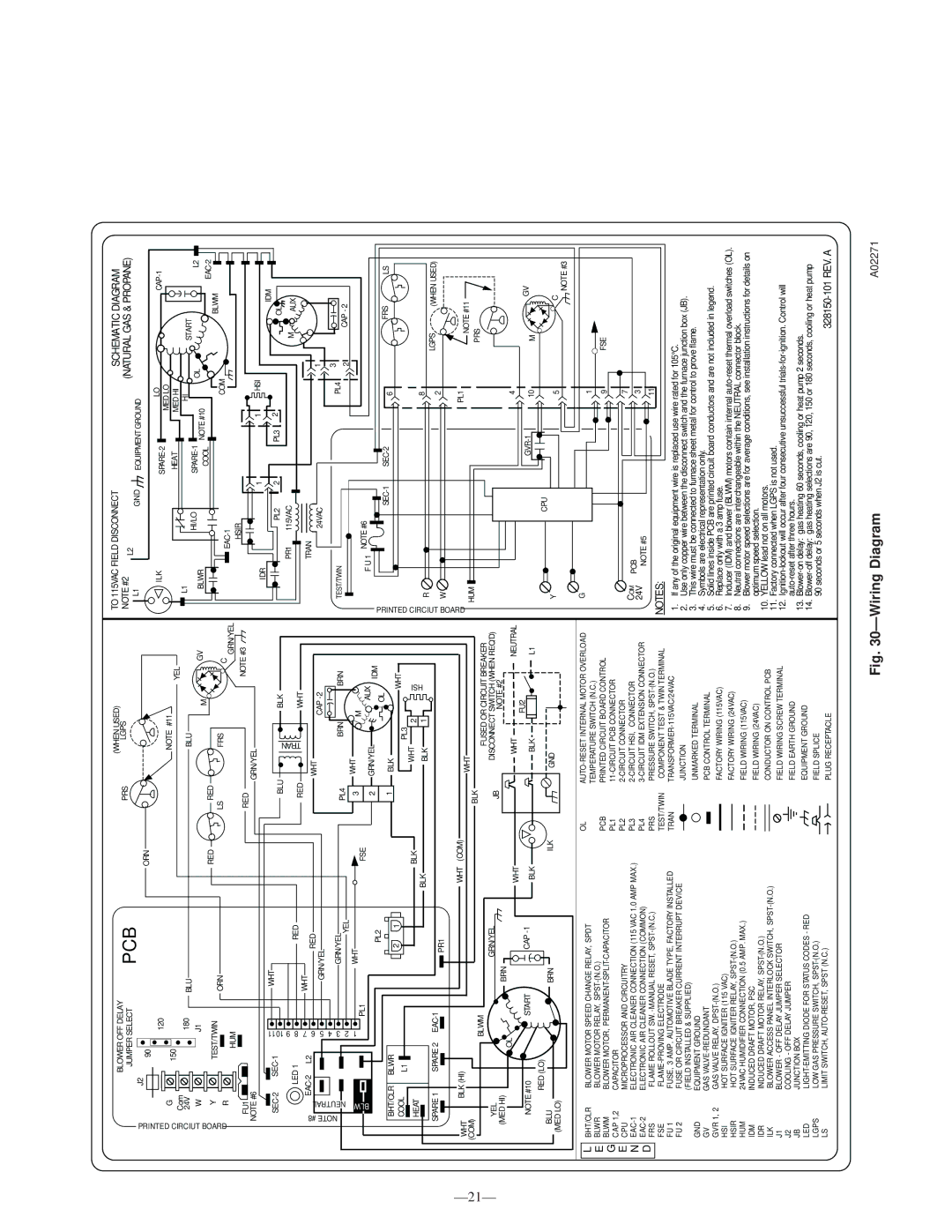
Fig. 30—Wiring Diagram

A02271

Page 21
Image 21
Bryant 340MAV instruction manual Pcb

340MAV specifications

The Bryant 340MAV is a standout model in the Bryant lineup, designed to provide exceptional comfort, efficiency, and performance for residential heating and cooling needs. This unit offers a perfect blend of innovative technology and user-friendly features, making it an ideal choice for homeowners seeking reliability and quality.

One of the defining characteristics of the Bryant 340MAV is its impressive efficiency rating. With a SEER (Seasonal Energy Efficiency Ratio) of up to 18, this model ensures that homeowners can enjoy effective cooling during the summer months while minimizing energy consumption. Similarly, the heating efficiency is notable, with a high AFUE (Annual Fuel Utilization Efficiency) rating. This makes the 340MAV an environmentally friendly option that also promotes cost savings on energy bills.

The 340MAV incorporates advanced technologies that enhance its performance. One such technology is the variable-speed compressor, which allows the system to adjust its output based on the demands of the home. This means that the unit operates more quietly and reduces energy usage by matching the cooling or heating output required. Additionally, the two-stage heating capability provides more consistent temperatures and improved comfort throughout the space.

Operating noise is a crucial factor in residential HVAC systems, and the Bryant 340MAV is designed with this in mind. Engineered for quiet operation, the unit features a sound-dampening design, including an insulated cabinet and a specially designed compressor that minimizes noise levels. Homeowners can enjoy a comfortable indoor climate without the disruptive racket often associated with traditional systems.

Furthermore, the Bryant 340MAV is equipped with a durable all-aluminum coil, which improves heat transfer efficiency while also being resistant to corrosion. This characteristic contributes to the longevity of the unit, ensuring that it can withstand various environmental factors without compromising performance.

Another key feature is the advanced control options that the Bryant 340MAV offers. Integration with smart thermostats allows homeowners to monitor and adjust their HVAC system remotely, ensuring optimal comfort at all times. Additionally, the system is compatible with Bryant's Perfect Airâ„¢ filtration system, enhancing indoor air quality by reducing pollutants and allergens.

In summary, the Bryant 340MAV is a high-efficiency heating and cooling solution that brings together cutting-edge technology, quiet operation, and user-friendly features. With its focus on comfort and energy savings, it stands out as a prime choice for homeowners looking to invest in a reliable HVAC system.