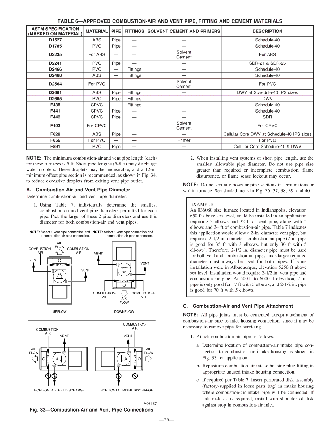
340MAV specifications
The Bryant 340MAV is a standout model in the Bryant lineup, designed to provide exceptional comfort, efficiency, and performance for residential heating and cooling needs. This unit offers a perfect blend of innovative technology and user-friendly features, making it an ideal choice for homeowners seeking reliability and quality.One of the defining characteristics of the Bryant 340MAV is its impressive efficiency rating. With a SEER (Seasonal Energy Efficiency Ratio) of up to 18, this model ensures that homeowners can enjoy effective cooling during the summer months while minimizing energy consumption. Similarly, the heating efficiency is notable, with a high AFUE (Annual Fuel Utilization Efficiency) rating. This makes the 340MAV an environmentally friendly option that also promotes cost savings on energy bills.
The 340MAV incorporates advanced technologies that enhance its performance. One such technology is the variable-speed compressor, which allows the system to adjust its output based on the demands of the home. This means that the unit operates more quietly and reduces energy usage by matching the cooling or heating output required. Additionally, the two-stage heating capability provides more consistent temperatures and improved comfort throughout the space.
Operating noise is a crucial factor in residential HVAC systems, and the Bryant 340MAV is designed with this in mind. Engineered for quiet operation, the unit features a sound-dampening design, including an insulated cabinet and a specially designed compressor that minimizes noise levels. Homeowners can enjoy a comfortable indoor climate without the disruptive racket often associated with traditional systems.
Furthermore, the Bryant 340MAV is equipped with a durable all-aluminum coil, which improves heat transfer efficiency while also being resistant to corrosion. This characteristic contributes to the longevity of the unit, ensuring that it can withstand various environmental factors without compromising performance.
Another key feature is the advanced control options that the Bryant 340MAV offers. Integration with smart thermostats allows homeowners to monitor and adjust their HVAC system remotely, ensuring optimal comfort at all times. Additionally, the system is compatible with Bryant's Perfect Air™ filtration system, enhancing indoor air quality by reducing pollutants and allergens.
In summary, the Bryant 340MAV is a high-efficiency heating and cooling solution that brings together cutting-edge technology, quiet operation, and user-friendly features. With its focus on comfort and energy savings, it stands out as a prime choice for homeowners looking to invest in a reliable HVAC system.

