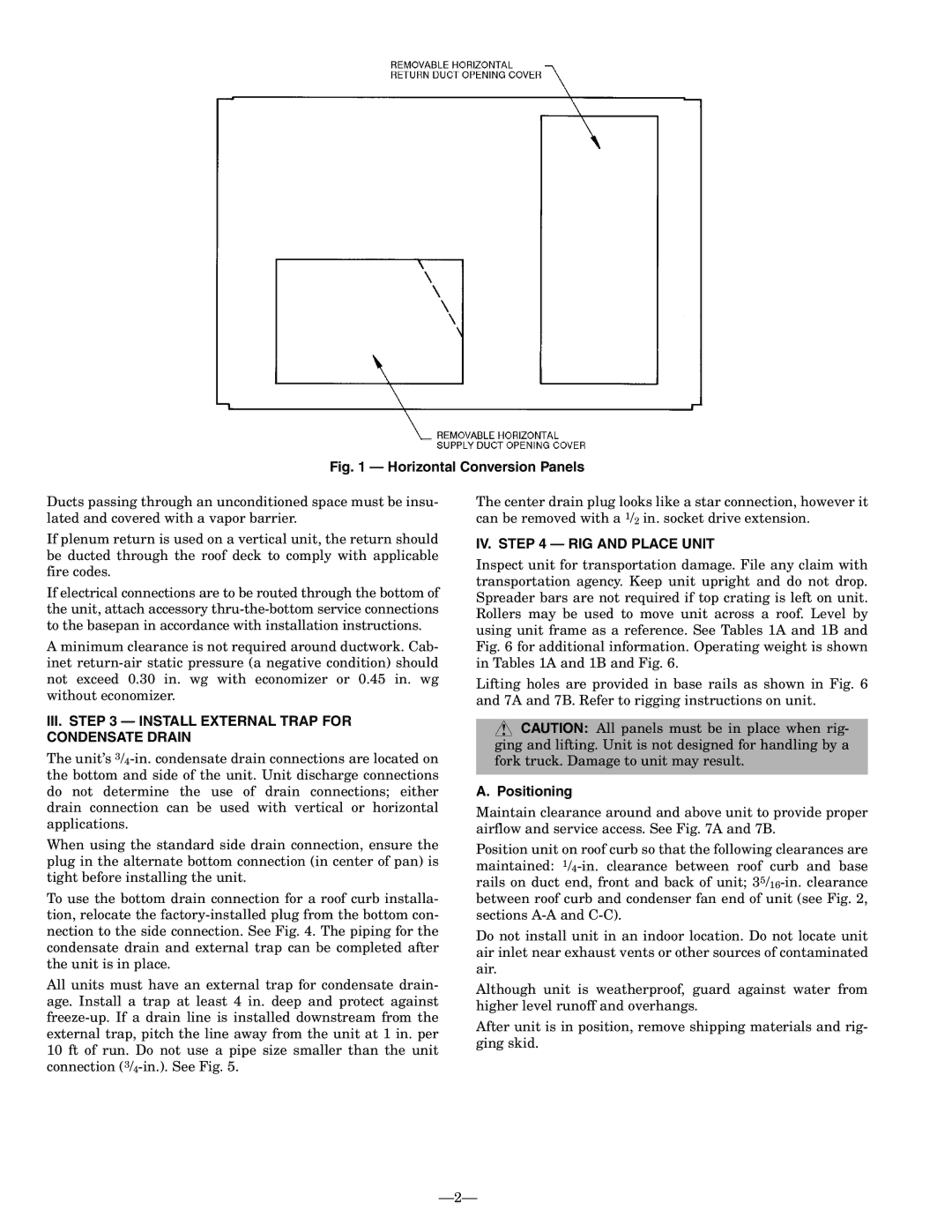
Fig. 1 — Horizontal Conversion Panels

Ducts passing through an unconditioned space must be insu- lated and covered with a vapor barrier.

If plenum return is used on a vertical unit, the return should be ducted through the roof deck to comply with applicable fire codes.

If electrical connections are to be routed through the bottom of the unit, attach accessory thru-the-bottom service connections to the basepan in accordance with installation instructions.

A minimum clearance is not required around ductwork. Cab- inet return-air static pressure (a negative condition) should not exceed 0.30 in. wg with economizer or 0.45 in. wg without economizer.

III.STEP 3 — INSTALL EXTERNAL TRAP FOR CONDENSATE DRAIN

The unit’s 3/4-in. condensate drain connections are located on the bottom and side of the unit. Unit discharge connections do not determine the use of drain connections; either drain connection can be used with vertical or horizontal applications.

When using the standard side drain connection, ensure the plug in the alternate bottom connection (in center of pan) is tight before installing the unit.

To use the bottom drain connection for a roof curb installa- tion, relocate the factory-installed plug from the bottom con- nection to the side connection. See Fig. 4. The piping for the condensate drain and external trap can be completed after the unit is in place.

All units must have an external trap for condensate drain- age. Install a trap at least 4 in. deep and protect against freeze-up. If a drain line is installed downstream from the external trap, pitch the line away from the unit at 1 in. per 10 ft of run. Do not use a pipe size smaller than the unit connection (3/4-in.). See Fig. 5.

The center drain plug looks like a star connection, however it can be removed with a 1/2 in. socket drive extension.

IV. STEP 4 — RIG AND PLACE UNIT

Inspect unit for transportation damage. File any claim with transportation agency. Keep unit upright and do not drop. Spreader bars are not required if top crating is left on unit. Rollers may be used to move unit across a roof. Level by using unit frame as a reference. See Tables 1A and 1B and Fig. 6 for additional information. Operating weight is shown in Tables 1A and 1B and Fig. 6.

Lifting holes are provided in base rails as shown in Fig. 6 and 7A and 7B. Refer to rigging instructions on unit.

CAUTION: All panels must be in place when rig- ging and lifting. Unit is not designed for handling by a fork truck. Damage to unit may result.

A. Positioning

Maintain clearance around and above unit to provide proper airflow and service access. See Fig. 7A and 7B.

Position unit on roof curb so that the following clearances are maintained: 1/4-in. clearance between roof curb and base rails on duct end, front and back of unit; 35/16-in. clearance between roof curb and condenser fan end of unit (see Fig. 2, sections A-A and C-C).

Do not install unit in an indoor location. Do not locate unit air inlet near exhaust vents or other sources of contaminated air.

Although unit is weatherproof, guard against water from higher level runoff and overhangs.

After unit is in position, remove shipping materials and rig- ging skid.

2

Page 2
Image 2
Bryant 558F installation instructions III. Install External Trap for Condensate Drain, IV. RIG and Place Unit, Positioning

558F specifications

The Bryant 558F is a highly efficient and versatile gas furnace designed to provide reliable heating for residential spaces. Known for its exceptional performance and advanced technology, the 558F caters to homeowners looking for comfort, efficiency, and sustainability in their heating solutions.

One of the primary features of the Bryant 558F is its two-stage heating capability. This system allows the furnace to operate at different levels of output, optimizing energy consumption based on the heating demands of the home. By operating at a lower stage most of the time, the 558F can maintain consistent indoor temperatures while using less energy, leading to reduced utility bills.

The furnace is also equipped with aVariable Speed ECM blower motor. This feature provides enhanced air distribution and comfort by allowing for more precise control over airflow. The variable speed operation ensures that the furnace can adjust to the heating needs of the space without the constant on-off cycling, promoting quieter operation and better efficiency.

In terms of efficiency ratings, the Bryant 558F boasts an impressive Annual Fuel Utilization Efficiency (AFUE) rating of up to 96%. This high rating indicates that the furnace converts a significant portion of its fuel into usable heat, making it an environmentally friendly choice. With lower greenhouse gas emissions, homeowners not only benefit from cost savings but also contribute to reducing their carbon footprint.

Additionally, the furnace incorporates advanced combustion technology, including a durable heat exchanger designed for longevity and efficiency. This component is vital for maximizing heat transfer while minimizing heat loss, contributing to the overall performance of the unit.

The Bryant 558F is compatible with the manufacturer's Infinity System control, providing homeowners with a user-friendly interface to manage their heating system effectively. This compatibility allows for the integration of smart home technology, enabling remote access and programmable settings for added convenience.

Installation and maintenance of the Bryant 558F are straightforward, thanks to its compact design and thoughtful layout. Homeowners can find peace of mind knowing that service and upkeep are manageable, prolonging the life of the furnace.

In summary, the Bryant 558F gas furnace combines efficiency, advanced technology, and reliability to provide exceptional indoor comfort. With its two-stage heating, variable speed blower motor, and high AFUE rating, the 558F stands out as an optimal heating solution for modern homes seeking both performance and sustainability.