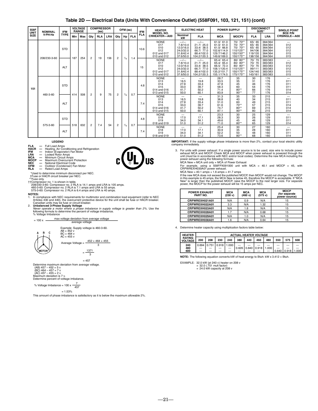
Table 2D — Electrical Data (Units With Convenience Outlet) (558F091, 103, 121, 151) (cont)

558F


VOLTAGE

COMPRESSOR

OFM (ea)


HEATER

ELECTRIC HEAT

POWER SUPPLY

DISCONNECT

SINGLE POINT

NOMINAL

IFM

RANGE


(ea)


IFM


SIZE*

UNIT


MODEL NO.


BOX P/N

SIZE

V-PH-Hz

TYPE

Min

Max

Qty

RLA

LRA

Qty

Hp

FLA

FLA

CRHEATER---A00

Nominal

FLA

MCA

MOCP†

FLA

LRA

CRSINGLE---A00


kW


NONE

—/—

—/—

61.0/ 61.0

70/ 70**

65/ 65

364/364


017

7.8/10.4

21.7/

25.0

61.0/

61.0

70/

70**

65/

65

364/364

012


STD


10.6

010

12.0/16.0

33.4/

38.5

61.0/

66.8

70/

70**

65/

65

364/364

012


012

24.0/32.0

66.7/

77.0

102.6/114.9

110/125**

94/106

364/364

012


012 and 017

31.8/42.4

88.4/102.0

129.7/146.2

150/150**

119/135

364/364

015


208/230-3-60


187

254

2

19

156

2

1/4

1.4


010 and 012

37.6/50.0

104.2/120.3

149.6/169.0

150/175**

138/156

364/364

015


NONE

—/—

—/—

65.4/ 65.4

80/ 80**

70/ 70

383/383


017

7.8/10.4

21.7/

25.0

65.4/

65.4

80/

80**

70/

70

383/383

012


ALT


15

010

12.0/16.0

33.4/

38.5

66.5/

72.3

80/

80**

70/

70

383/383

012


012

24.0/32.0

66.7/

77.0

108.1/120.4

110/125**

99/111

383/383

012


012 and 017

31.8/42.4

88.4/102.0

135.2/151.7

150/175**

124/140

383/383

015


010 and 012

37.6/50.0

104.2/120.3

155.1/174.5

175/175**

143/161

383/383

015


NONE


28.7

35

30


176


013

16.5

19.8

33.5

35

31


176

011


STD


4.8

014

27.8

33.4

47.8

45

46


176

011


015

33.0

39.7

58.3

60

54


176

011

151


014 and 016

41.7

50.2

71.4

80**

66


176

014


460-3-60


414

508

2

9

75

2

1/4

0.7


013 and 015

50.0

60.1

83.9

90**

77


176

014


NONE


31.3

35

33


215


013

16.5

19.8

36.8

40

34


215

011


ALT


7.4

014

27.8

33.4

51.0

60

49


215

011


015

33.0

39.7

61.6

70**

57


215

014


014 and 016

41.7

50.2

74.7

80**

69


215

014


013 and 015

50.0

60.1

87.1

90**

80


215

014


NONE


23.3

30

25


129


STD


4.8

018

17.0

17.1

28.3

30

26


129

011


019

34.0

34.1

49.6

45

46


129

011


575-3-60


518

632

2

7.4

54

2

1/4

0.7


018 and 019

51.0

51.2

71.0

80**

65


129

014


NONE


25.4

30

27


160


ALT


7.4

018

17.0

17.1

30.9

35

28


160

011


019

34.0

34.1

52.2

50

48


160

011


018 and 019

51.0

51.2

73.6

80**

68


160

014


LEGEND

FLA

Full Load Amps

HACR

Heating, Air Conditioning and Refrigeration

IFM

Indoor (Evaporator) Fan Motor

LRA

Locked Rotor Amps

MCA

Minimum Circuit Amps

MOCP

Maximum Overcurrent Protection

NEC

National Electrical Code

OFM

Outdoor (Condenser) Fan Motor

RLA

Rated Load Amps

*Used to determine minimum disconnect per NEC. †Fuse or HACR circuit breaker per NEC.

**Fuse only.

††Compressor no. 1 is shown in table.

208/230-3-60: Compressor no. 2 RLA is 14.1 amps and LRA is 105 amps.

460-3-60: Compressor no. 2 RLA is 7.1 amps and LRA is 55 amps.

575-3-60: Compressor no. 2 RLA is 6.4 amps and LRA is 40 amps.

NOTES:

1.In compliance with NEC requirements for multimotor and combination load equipment (refer to NEC Articles 430 and 440), the overcurrent protective device for the unit shall be fuse or HACR breaker. Canadian units may be fuse or circuit breaker.

2.Unbalanced 3-Phase Supply Voltage

Never operate a motor where a phase imbalance in supply voltage is greater than 2%. Use the following formula to determine the percent of voltage imbalance.

% Voltage Imbalance

max voltage deviation from average voltage

= 100 x

average voltage

Example: Supply voltage is 460-3-60.

AB = 452 v

BC = 464 v

AC = 455 v

452 + 464 + 455

Average Voltage =

3

=1371

3

=457

Determine maximum deviation from average voltage. (AB) 457 – 452 = 5 v

(BC) 464 – 457 = 7 v (AC) 457 – 455 = 2 v Maximum deviation is 7 v.

Determine percent of voltage imbalance.

IMPORTANT: If the supply voltage phase imbalance is more than 2%, contact your local electric utility company immediately.

3.For units with power exhaust: If a single power source is to be used, size wire to include power exhaust MCA and MOCP. Check MCA and MOCP when power exhaust is powered through the unit (must be in accordance with NEC and/or local codes). Determine the new MCA including the power exhaust using the following formula:

MCA New = MCA unit only + MCA of Power Exhaust

For example, using a 558FPX091000 unit with MCA = 40.1 and MOCP = 45, with CRPWREXH030A01 power exhaust.

MCA New = 40.1 amps + 1.6 amps = 41.7 amps

If the new MCA does not exceed the published MOCP, then MOCP would not change. The MOCP in this example is 45 amps, the MCA New is below 45, therefore the MOCP is acceptable. If “MCA New” is larger than the published MOCP, raise the MOCP to the next larger size. For separate power, the MOCP for the power exhaust will be 15 amps per NEC.

POWER EXHAUST

MCA

MCA

MCA

MOCP

(for separate

PART NO.

(230 v)

(460 v)

(575 v)

power source)


CRPWREXH021A01

N/A

0.9

N/A

15

CRPWREXH022A01

3.3

N/A

1.32

15

CRPWREXH023A01

N/A

1.8

N/A

15

CRPWREXH028A01

1.7

N/A

0.68

15

CRPWREXH029A01

N/A

1.0

N/A

15

CRPWREXH030A01

1.6

N/A

0.64

15

4. Determine heater capacity using multiplication factors table below:

HEATER


ACTUAL HEATER VOLTAGE


RATING

200

208

230

240

380

440

460

480

550

575

600

VOLTAGE

240

0.694

0.751

0.918

1.000

480

0.626

0.840

0.918

1.000

600

0.840

0.918

1.000

NOTE: The following equation converts kW of heat energy to Btuh: kW x 3.412 = Btuh.

EXAMPLE: 32.0 kW (at 240 v) heater on 208 v

=32.0 (.751 mult factor)

=24.0 kW capacity at 208 v

% Voltage Imbalance = 100 x

7

457

= 1.53%

This amount of phase imbalance is satisfactory as it is below the maximum allowable 2%.

21

Page 21
Image 21
Bryant 558F installation instructions 61.0 364/364 017 10.4 21.7 25.0 012

558F specifications

The Bryant 558F is a highly efficient and versatile gas furnace designed to provide reliable heating for residential spaces. Known for its exceptional performance and advanced technology, the 558F caters to homeowners looking for comfort, efficiency, and sustainability in their heating solutions.

One of the primary features of the Bryant 558F is its two-stage heating capability. This system allows the furnace to operate at different levels of output, optimizing energy consumption based on the heating demands of the home. By operating at a lower stage most of the time, the 558F can maintain consistent indoor temperatures while using less energy, leading to reduced utility bills.

The furnace is also equipped with aVariable Speed ECM blower motor. This feature provides enhanced air distribution and comfort by allowing for more precise control over airflow. The variable speed operation ensures that the furnace can adjust to the heating needs of the space without the constant on-off cycling, promoting quieter operation and better efficiency.

In terms of efficiency ratings, the Bryant 558F boasts an impressive Annual Fuel Utilization Efficiency (AFUE) rating of up to 96%. This high rating indicates that the furnace converts a significant portion of its fuel into usable heat, making it an environmentally friendly choice. With lower greenhouse gas emissions, homeowners not only benefit from cost savings but also contribute to reducing their carbon footprint.

Additionally, the furnace incorporates advanced combustion technology, including a durable heat exchanger designed for longevity and efficiency. This component is vital for maximizing heat transfer while minimizing heat loss, contributing to the overall performance of the unit.

The Bryant 558F is compatible with the manufacturer's Infinity System control, providing homeowners with a user-friendly interface to manage their heating system effectively. This compatibility allows for the integration of smart home technology, enabling remote access and programmable settings for added convenience.

Installation and maintenance of the Bryant 558F are straightforward, thanks to its compact design and thoughtful layout. Homeowners can find peace of mind knowing that service and upkeep are manageable, prolonging the life of the furnace.

In summary, the Bryant 558F gas furnace combines efficiency, advanced technology, and reliability to provide exceptional indoor comfort. With its two-stage heating, variable speed blower motor, and high AFUE rating, the 558F stands out as an optimal heating solution for modern homes seeking both performance and sustainability.