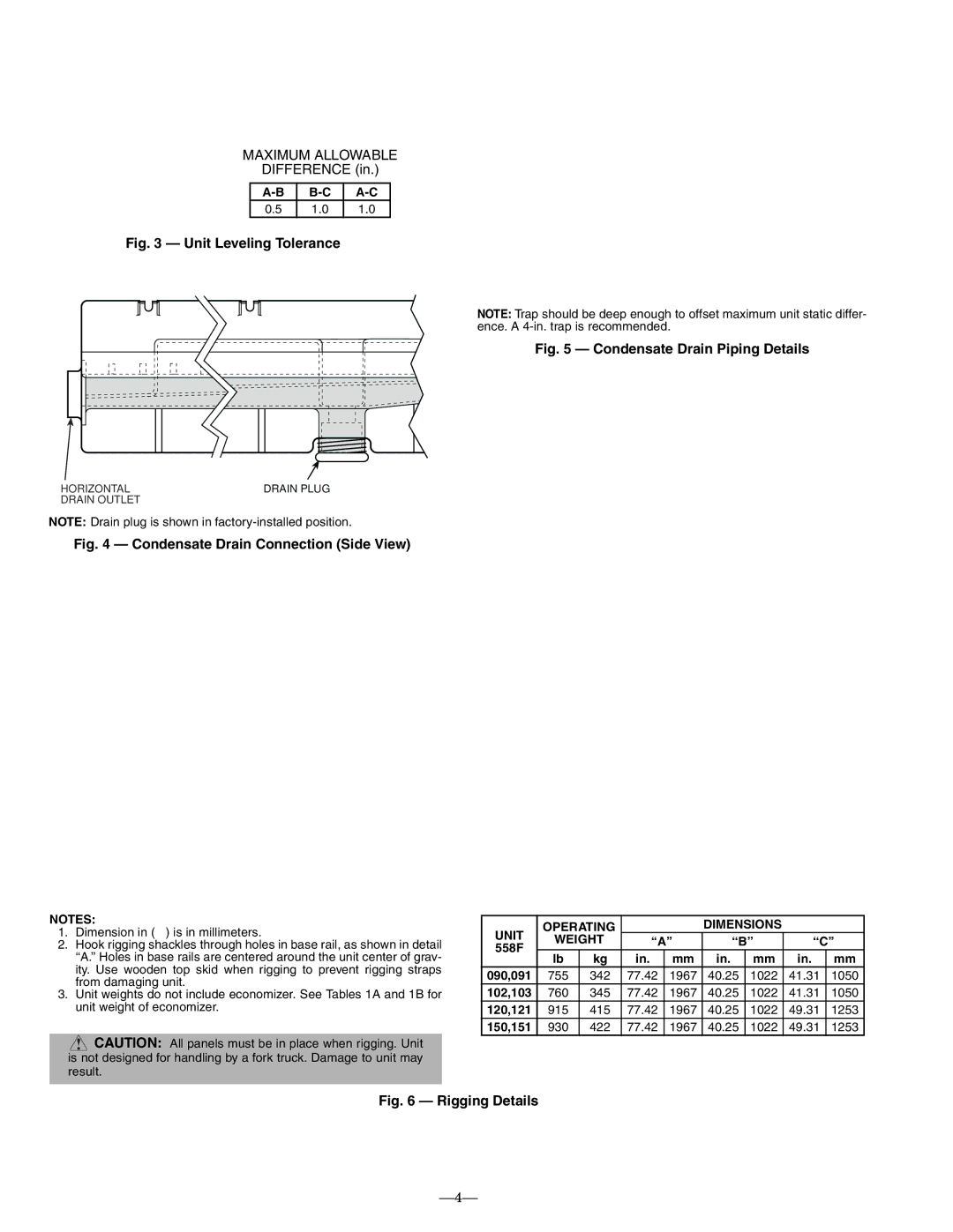
558F specifications
The Bryant 558F is a highly efficient and versatile gas furnace designed to provide reliable heating for residential spaces. Known for its exceptional performance and advanced technology, the 558F caters to homeowners looking for comfort, efficiency, and sustainability in their heating solutions.One of the primary features of the Bryant 558F is its two-stage heating capability. This system allows the furnace to operate at different levels of output, optimizing energy consumption based on the heating demands of the home. By operating at a lower stage most of the time, the 558F can maintain consistent indoor temperatures while using less energy, leading to reduced utility bills.
The furnace is also equipped with aVariable Speed ECM blower motor. This feature provides enhanced air distribution and comfort by allowing for more precise control over airflow. The variable speed operation ensures that the furnace can adjust to the heating needs of the space without the constant on-off cycling, promoting quieter operation and better efficiency.
In terms of efficiency ratings, the Bryant 558F boasts an impressive Annual Fuel Utilization Efficiency (AFUE) rating of up to 96%. This high rating indicates that the furnace converts a significant portion of its fuel into usable heat, making it an environmentally friendly choice. With lower greenhouse gas emissions, homeowners not only benefit from cost savings but also contribute to reducing their carbon footprint.
Additionally, the furnace incorporates advanced combustion technology, including a durable heat exchanger designed for longevity and efficiency. This component is vital for maximizing heat transfer while minimizing heat loss, contributing to the overall performance of the unit.
The Bryant 558F is compatible with the manufacturer's Infinity System control, providing homeowners with a user-friendly interface to manage their heating system effectively. This compatibility allows for the integration of smart home technology, enabling remote access and programmable settings for added convenience.
Installation and maintenance of the Bryant 558F are straightforward, thanks to its compact design and thoughtful layout. Homeowners can find peace of mind knowing that service and upkeep are manageable, prolonging the life of the furnace.
In summary, the Bryant 558F gas furnace combines efficiency, advanced technology, and reliability to provide exceptional indoor comfort. With its two-stage heating, variable speed blower motor, and high AFUE rating, the 558F stands out as an optimal heating solution for modern homes seeking both performance and sustainability.

