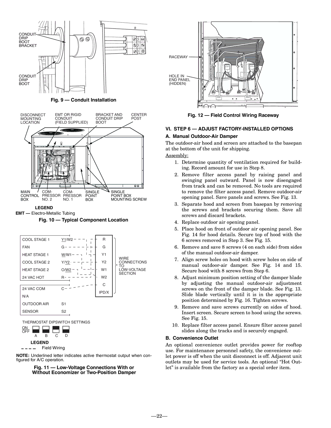
Fig. 9 — Conduit Installation

DISCONNECT


EMT OR RIGID

BRACKET AND

CENTER

MOUNTING


CONDUIT

CONDUIT DRIP

POST

LOCATION


(FIELD SUPPLIED)

BOOT


MAIN

COM-

COM-

SINGLE

SINGLE

CONTROL

PRESSOR

PRESSOR

POINT

POINT BOX

BOX

NO. 2

NO. 1

BOX

MOUNTING SCREW

LEGEND

EMT — Electro-Metallic Tubing

Fig. 10 — Typical Component Location

RACEWAY

HOLE IN END PANEL (HIDDEN)

Fig. 12 — Field Control Wiring Raceway

VI. STEP 6 — ADJUST FACTORY-INSTALLED OPTIONS A. Manual Outdoor-Air Damper

The outdoor-air hood and screen are attached to the basepan at the bottom of the unit for shipping.

Assembly:

1.

Determine quantity of ventilation required for build-


ing. Record amount for use in Step 8.

2.

Remove filter access panel by raising panel and


swinging panel outward. Panel is now disengaged


from track and can be removed. No tools are required


to remove the filter access panel. Remove outdoor-air


opening panel. Save panels and screws. See Fig. 13.

3.

Separate hood and screen from basepan by removing


the screws and brackets securing them. Save all


screws and discard brackets.

4.

Replace outdoor air opening panel.

5.

Place hood on front of outdoor air opening panel. See


Fig. 14 for hood details. Secure top of hood with the

COOL STAGE 1

Y1/W2

FAN

G

HEAT STAGE 1

W/W1

COOL STAGE 2

Y/Y2

HEAT STAGE 2

O/W2

24 VAC HOT

R

24 VAC COM

C

N/A


OUTDOOR AIR

S1

SENSOR

S2

R

G

Y1

Y2

W1

W2

C

IPD/X

WIRE CONNECTIONS TO LOW-VOLTAGE SECTION


6 screws removed in Step 3. See Fig. 15.

6.

Remove and save 8 screws (4 on each side) from sides


of the manual outdoor-air damper.

7.

Align screw holes on hood with screw holes on side of


manual outdoor-air damper. See Fig. 14 and 15.


Secure hood with 8 screws from Step 6.

8.

Adjust minimum position setting of the damper blade


by adjusting the manual outdoor-air adjustment


screws on the front of the damper blade. See Fig. 13.


Slide blade vertically until it is in the appropriate


position determined by Fig. 16. Tighten screws.

9.

Remove and save screws currently on sides of hood.


Insert screen. Secure screen to hood using the screws.


See Fig. 15.

THERMOSTAT DIPSWITCH SETTINGS

ON

OFF

A B C D

LEGEND

Field Wiring

NOTE: Underlined letter indicates active thermostat output when con- figured for A/C operation.

Fig. 11 — Low-Voltage Connections With or Without Economizer or Two-Position Damper

10. Replace filter access panel. Ensure filter access panel

slides along the tracks and is securely engaged.

B. Convenience Outlet

An optional convenience outlet provides power for rooftop use. For maintenance personnel safety, the convenience out- let power is off when the unit disconnect is off. Adjacent unit outlets may be used for service tools. An optional “Hot Out- let” is available from the factory as a special order item.

22

Page 22
Image 22
Bryant 558F installation instructions Conduit Installation, Convenience Outlet

558F specifications

The Bryant 558F is a highly efficient and versatile gas furnace designed to provide reliable heating for residential spaces. Known for its exceptional performance and advanced technology, the 558F caters to homeowners looking for comfort, efficiency, and sustainability in their heating solutions.

One of the primary features of the Bryant 558F is its two-stage heating capability. This system allows the furnace to operate at different levels of output, optimizing energy consumption based on the heating demands of the home. By operating at a lower stage most of the time, the 558F can maintain consistent indoor temperatures while using less energy, leading to reduced utility bills.

The furnace is also equipped with aVariable Speed ECM blower motor. This feature provides enhanced air distribution and comfort by allowing for more precise control over airflow. The variable speed operation ensures that the furnace can adjust to the heating needs of the space without the constant on-off cycling, promoting quieter operation and better efficiency.

In terms of efficiency ratings, the Bryant 558F boasts an impressive Annual Fuel Utilization Efficiency (AFUE) rating of up to 96%. This high rating indicates that the furnace converts a significant portion of its fuel into usable heat, making it an environmentally friendly choice. With lower greenhouse gas emissions, homeowners not only benefit from cost savings but also contribute to reducing their carbon footprint.

Additionally, the furnace incorporates advanced combustion technology, including a durable heat exchanger designed for longevity and efficiency. This component is vital for maximizing heat transfer while minimizing heat loss, contributing to the overall performance of the unit.

The Bryant 558F is compatible with the manufacturer's Infinity System control, providing homeowners with a user-friendly interface to manage their heating system effectively. This compatibility allows for the integration of smart home technology, enabling remote access and programmable settings for added convenience.

Installation and maintenance of the Bryant 558F are straightforward, thanks to its compact design and thoughtful layout. Homeowners can find peace of mind knowing that service and upkeep are manageable, prolonging the life of the furnace.

In summary, the Bryant 558F gas furnace combines efficiency, advanced technology, and reliability to provide exceptional indoor comfort. With its two-stage heating, variable speed blower motor, and high AFUE rating, the 558F stands out as an optimal heating solution for modern homes seeking both performance and sustainability.