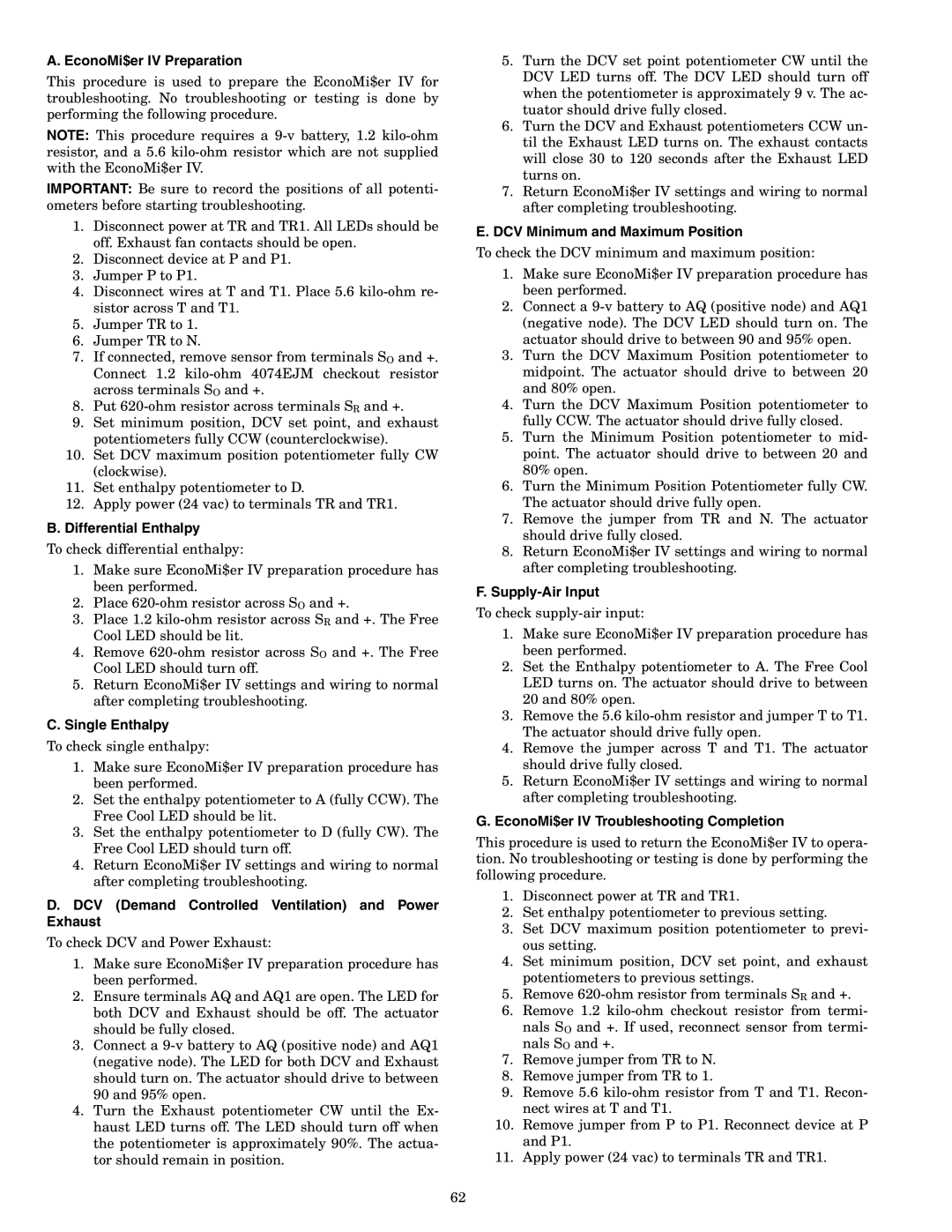
A. EconoMi$er IV Preparation

This procedure is used to prepare the EconoMi$er IV for troubleshooting. No troubleshooting or testing is done by performing the following procedure.

NOTE: This procedure requires a 9-v battery, 1.2 kilo-ohm resistor, and a 5.6 kilo-ohm resistor which are not supplied with the EconoMi$er IV.

IMPORTANT: Be sure to record the positions of all potenti- ometers before starting troubleshooting.

1.Disconnect power at TR and TR1. All LEDs should be off. Exhaust fan contacts should be open.

2.Disconnect device at P and P1.

3.Jumper P to P1.

4.Disconnect wires at T and T1. Place 5.6 kilo-ohm re- sistor across T and T1.

5.Jumper TR to 1.

6.Jumper TR to N.

7.If connected, remove sensor from terminals SO and +. Connect 1.2 kilo-ohm 4074EJM checkout resistor across terminals SO and +.

8.Put 620-ohm resistor across terminals SR and +.

9.Set minimum position, DCV set point, and exhaust potentiometers fully CCW (counterclockwise).

10.Set DCV maximum position potentiometer fully CW (clockwise).

11.Set enthalpy potentiometer to D.

12.Apply power (24 vac) to terminals TR and TR1.

B. Differential Enthalpy

To check differential enthalpy:

1.Make sure EconoMi$er IV preparation procedure has been performed.

2.Place 620-ohm resistor across SO and +.

3.Place 1.2 kilo-ohm resistor across SR and +. The Free Cool LED should be lit.

4.Remove 620-ohm resistor across SO and +. The Free Cool LED should turn off.

5.Return EconoMi$er IV settings and wiring to normal after completing troubleshooting.

C.Single Enthalpy

To check single enthalpy:

1.Make sure EconoMi$er IV preparation procedure has been performed.

2.Set the enthalpy potentiometer to A (fully CCW). The Free Cool LED should be lit.

3.Set the enthalpy potentiometer to D (fully CW). The Free Cool LED should turn off.

4.Return EconoMi$er IV settings and wiring to normal after completing troubleshooting.

D.DCV (Demand Controlled Ventilation) and Power Exhaust

To check DCV and Power Exhaust:

1.Make sure EconoMi$er IV preparation procedure has been performed.

2.Ensure terminals AQ and AQ1 are open. The LED for both DCV and Exhaust should be off. The actuator should be fully closed.

3.Connect a 9-v battery to AQ (positive node) and AQ1 (negative node). The LED for both DCV and Exhaust should turn on. The actuator should drive to between 90 and 95% open.

4.Turn the Exhaust potentiometer CW until the Ex- haust LED turns off. The LED should turn off when the potentiometer is approximately 90%. The actua- tor should remain in position.

5.Turn the DCV set point potentiometer CW until the DCV LED turns off. The DCV LED should turn off when the potentiometer is approximately 9 v. The ac- tuator should drive fully closed.

6.Turn the DCV and Exhaust potentiometers CCW un- til the Exhaust LED turns on. The exhaust contacts will close 30 to 120 seconds after the Exhaust LED turns on.

7.Return EconoMi$er IV settings and wiring to normal after completing troubleshooting.

E.DCV Minimum and Maximum Position

To check the DCV minimum and maximum position:

1.Make sure EconoMi$er IV preparation procedure has been performed.

2.Connect a 9-v battery to AQ (positive node) and AQ1 (negative node). The DCV LED should turn on. The actuator should drive to between 90 and 95% open.

3.Turn the DCV Maximum Position potentiometer to midpoint. The actuator should drive to between 20 and 80% open.

4.Turn the DCV Maximum Position potentiometer to fully CCW. The actuator should drive fully closed.

5.Turn the Minimum Position potentiometer to mid- point. The actuator should drive to between 20 and 80% open.

6.Turn the Minimum Position Potentiometer fully CW. The actuator should drive fully open.

7.Remove the jumper from TR and N. The actuator should drive fully closed.

8.Return EconoMi$er IV settings and wiring to normal after completing troubleshooting.

F.Supply-Air Input

To check supply-air input:

1.Make sure EconoMi$er IV preparation procedure has been performed.

2.Set the Enthalpy potentiometer to A. The Free Cool LED turns on. The actuator should drive to between 20 and 80% open.

3.Remove the 5.6 kilo-ohm resistor and jumper T to T1. The actuator should drive fully open.

4.Remove the jumper across T and T1. The actuator should drive fully closed.

5.Return EconoMi$er IV settings and wiring to normal after completing troubleshooting.

G.EconoMi$er IV Troubleshooting Completion

This procedure is used to return the EconoMi$er IV to opera- tion. No troubleshooting or testing is done by performing the following procedure.

1.Disconnect power at TR and TR1.

2.Set enthalpy potentiometer to previous setting.

3.Set DCV maximum position potentiometer to previ- ous setting.

4.Set minimum position, DCV set point, and exhaust potentiometers to previous settings.

5.Remove 620-ohm resistor from terminals SR and +.

6.Remove 1.2 kilo-ohm checkout resistor from termi- nals SO and +. If used, reconnect sensor from termi- nals SO and +.

7.Remove jumper from TR to N.

8.Remove jumper from TR to 1.

9.Remove 5.6 kilo-ohm resistor from T and T1. Recon- nect wires at T and T1.

10.Remove jumper from P to P1. Reconnect device at P and P1.

11.Apply power (24 vac) to terminals TR and TR1.

62

Page 62
Image 62
Bryant 558F EconoMi$er IV Preparation, Differential Enthalpy, Single Enthalpy, DCV Minimum and Maximum Position

558F specifications

The Bryant 558F is a highly efficient and versatile gas furnace designed to provide reliable heating for residential spaces. Known for its exceptional performance and advanced technology, the 558F caters to homeowners looking for comfort, efficiency, and sustainability in their heating solutions.

One of the primary features of the Bryant 558F is its two-stage heating capability. This system allows the furnace to operate at different levels of output, optimizing energy consumption based on the heating demands of the home. By operating at a lower stage most of the time, the 558F can maintain consistent indoor temperatures while using less energy, leading to reduced utility bills.

The furnace is also equipped with aVariable Speed ECM blower motor. This feature provides enhanced air distribution and comfort by allowing for more precise control over airflow. The variable speed operation ensures that the furnace can adjust to the heating needs of the space without the constant on-off cycling, promoting quieter operation and better efficiency.

In terms of efficiency ratings, the Bryant 558F boasts an impressive Annual Fuel Utilization Efficiency (AFUE) rating of up to 96%. This high rating indicates that the furnace converts a significant portion of its fuel into usable heat, making it an environmentally friendly choice. With lower greenhouse gas emissions, homeowners not only benefit from cost savings but also contribute to reducing their carbon footprint.

Additionally, the furnace incorporates advanced combustion technology, including a durable heat exchanger designed for longevity and efficiency. This component is vital for maximizing heat transfer while minimizing heat loss, contributing to the overall performance of the unit.

The Bryant 558F is compatible with the manufacturer's Infinity System control, providing homeowners with a user-friendly interface to manage their heating system effectively. This compatibility allows for the integration of smart home technology, enabling remote access and programmable settings for added convenience.

Installation and maintenance of the Bryant 558F are straightforward, thanks to its compact design and thoughtful layout. Homeowners can find peace of mind knowing that service and upkeep are manageable, prolonging the life of the furnace.

In summary, the Bryant 558F gas furnace combines efficiency, advanced technology, and reliability to provide exceptional indoor comfort. With its two-stage heating, variable speed blower motor, and high AFUE rating, the 558F stands out as an optimal heating solution for modern homes seeking both performance and sustainability.