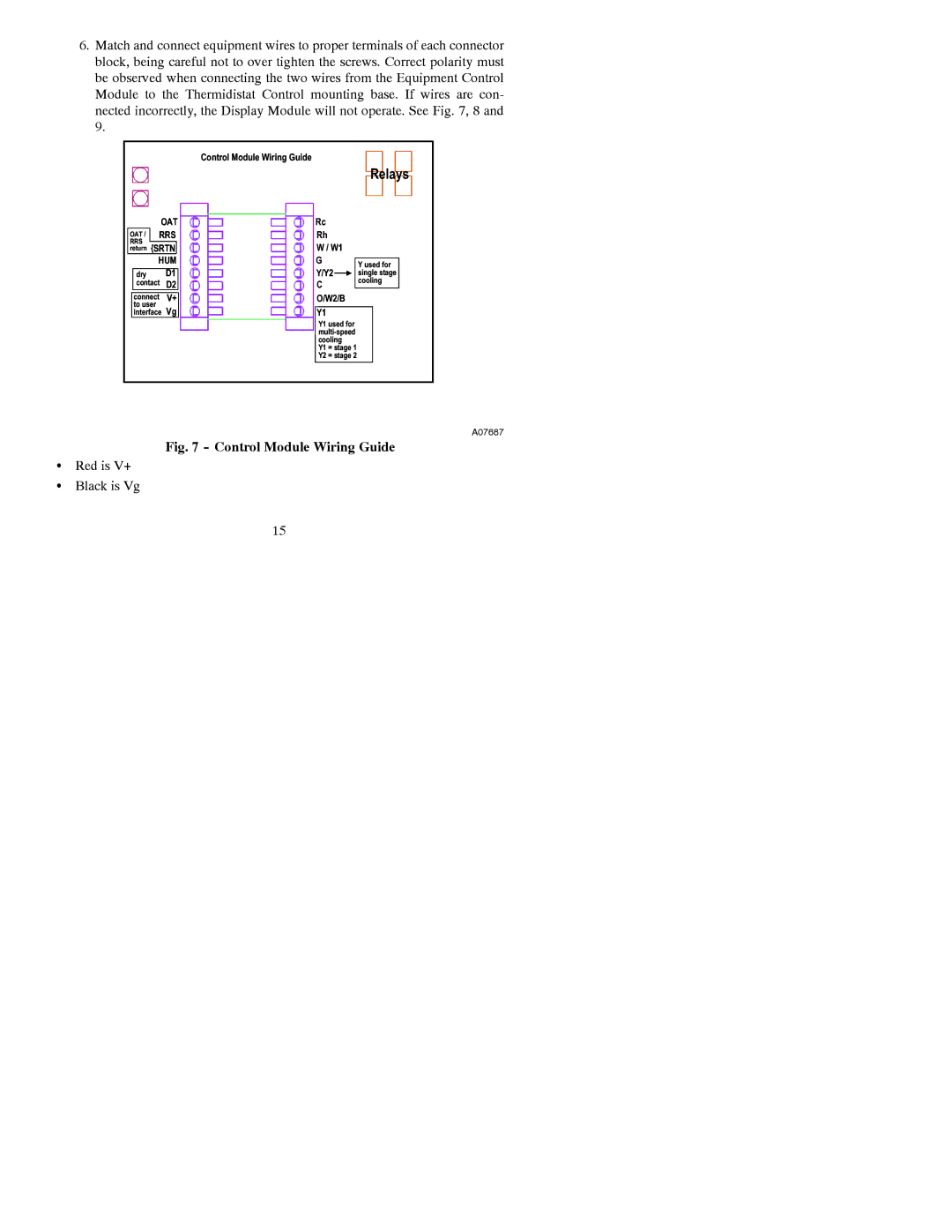
A07045, A07044 specifications
Bryant A07044 and A07045 are two advanced air conditioning units designed for both residential and commercial applications. These models are specifically engineered to provide high-efficiency cooling and optimal indoor comfort. With a focus on innovative technologies, they deliver reliability and performance that meet the demands of today's energy-conscious consumers.One of the standout features of the Bryant A07044 and A07045 is their impressive Energy Efficiency Ratio (EER). Both models are designed to consume less energy while providing substantial cooling power, which not only reduces utility bills but also contributes to a more sustainable environment. Their high-efficiency refrigerant systems ensure optimal performance even in extreme weather conditions.
Both models incorporate advanced inverter technology, which enables them to modulate cooling output based on the specific needs of the space. This allows for quieter operation and improved temperature control, ensuring that every room is maintained at the desired comfort level without unnecessary energy consumption. The variable-speed compressor adjusts the cooling output, providing more precise temperature regulation.
In terms of installation and integration, both Bryant A07044 and A07045 feature a compact design that makes them ideal for various spaces, whether it's a small apartment, a large commercial space, or anything in between. Their lightweight construction and flexible mounting options simplify the installation process, saving time and labor costs.
User-friendly controls are another significant feature of these models. They come equipped with a digital thermostat that allows homeowners and facility managers to easily program their desired temperatures. Additionally, many Bryant air conditioning units are compatible with smart home systems, enabling remote access and monitoring for added convenience.
Durability is a hallmark of Bryant's engineering, and both the A07044 and A07045 exemplify this commitment. They are constructed with high-quality materials and corrosion-resistant components, ensuring that they can withstand harsh environmental conditions. This longevity is complemented by Bryant's extensive warranty offerings, providing peace of mind for consumers.
In summary, the Bryant A07044 and A07045 air conditioning units stand out for their energy efficiency, advanced inverter technology, user-friendly controls, and robust construction. They are excellent choices for anyone seeking reliable and efficient cooling solutions for their homes or businesses.

