BT Versatility
Installation and Maintenance Manual
Cabling the unit
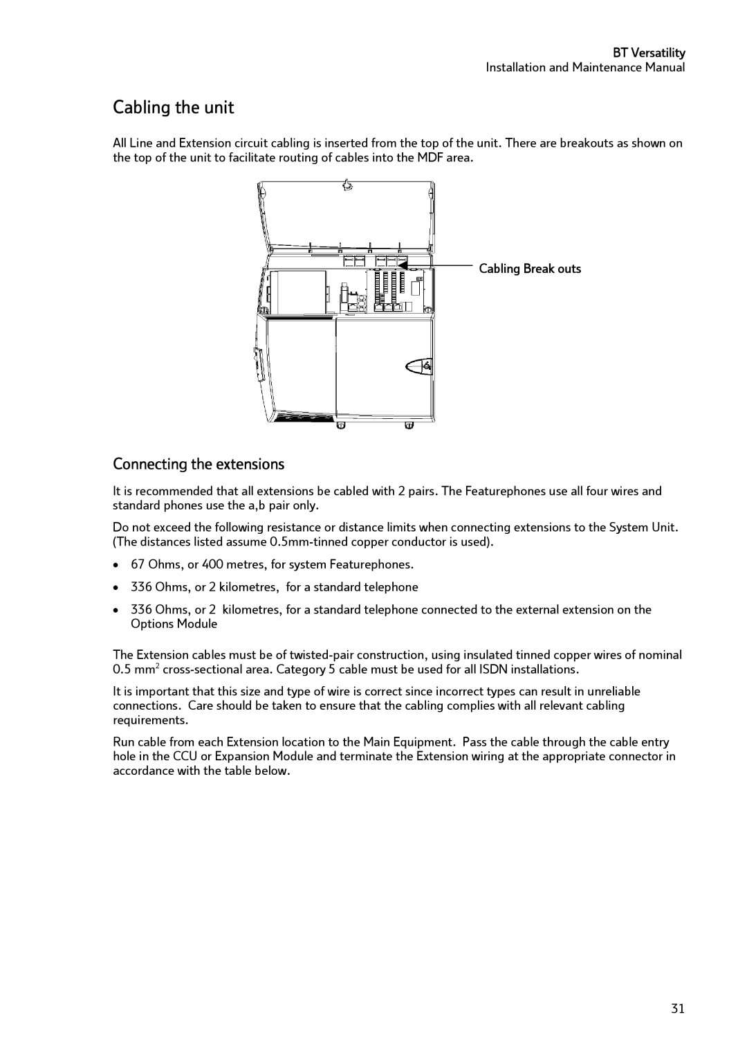
All Line and Extension circuit cabling is inserted from the top of the unit. There are breakouts as shown on the top of the unit to facilitate routing of cables into the MDF area.
Cabling Break outs
Connecting the extensions
It is recommended that all extensions be cabled with 2 pairs. The Featurephones use all four wires and standard phones use the a,b pair only.
Do not exceed the following resistance or distance limits when connecting extensions to the System Unit. (The distances listed assume
•67 Ohms, or 400 metres, for system Featurephones.
•336 Ohms, or 2 kilometres, for a standard telephone
•336 Ohms, or 2 kilometres, for a standard telephone connected to the external extension on the Options Module
The Extension cables must be of
It is important that this size and type of wire is correct since incorrect types can result in unreliable connections. Care should be taken to ensure that the cabling complies with all relevant cabling requirements.
Run cable from each Extension location to the Main Equipment. Pass the cable through the cable entry hole in the CCU or Expansion Module and terminate the Extension wiring at the appropriate connector in accordance with the table below.
31