BT Versatility
Installation and maintenance Manual
•The MOH Module may be used with all Systems provided they are running above software versions or later
The MOH Module provides an isolation barrier between the Extension Port and the Music Source and it MUST be installed if an External Music Source is being connected to an Extension Circuit
The MOH Module contains:
1.An adhesive pad for mounting in the MDF area of the CCU (see diagram)
2.A “bare wire” lead for connection to the AB connectors of an extension port
3.A 3.5mm Stereo jack for connection to the External Music Source
Installation and connection
1.Open the MDF Cover of the CCU
2.Remove the MOH Module from packaging
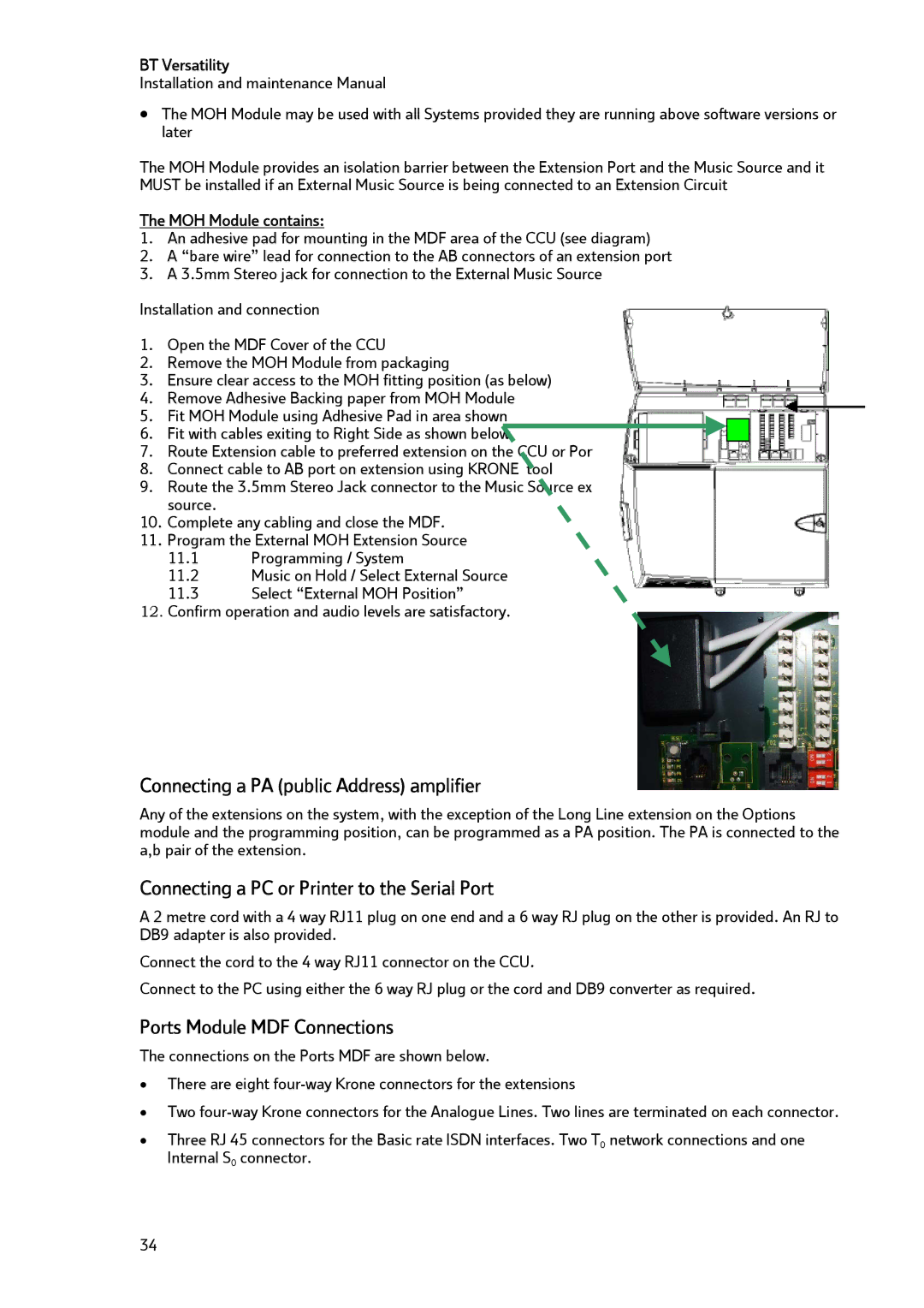
3.Ensure clear access to the MOH fitting position (as below)
4.Remove Adhesive Backing paper from MOH Module
5.Fit MOH Module using Adhesive Pad in area shown
6. Fit with cables exiting to Right Side as shown below
7.Route Extension cable to preferred extension on the CCU or Ports module
8.Connect cable to AB port on extension using KRONE tool
9.Route the 3.5mm Stereo Jack connector to the Music Source external to the system, and connect source.
10.Complete any cabling and close the MDF.
11.Program the External MOH Extension Source
11.1Programming / System
11.2Music on Hold / Select External Source
11.3Select “External MOH Position”
12.Confirm operation and audio levels are satisfactory.
Connecting a PA (public Address) amplifier
Any of the extensions on the system, with the exception of the Long Line extension on the Options module and the programming position, can be programmed as a PA position. The PA is connected to the a,b pair of the extension.
Connecting a PC or Printer to the Serial Port
A 2 metre cord with a 4 way RJ11 plug on one end and a 6 way RJ plug on the other is provided. An RJ to DB9 adapter is also provided.
Connect the cord to the 4 way RJ11 connector on the CCU.
Connect to the PC using either the 6 way RJ plug or the cord and DB9 converter as required.
Ports Module MDF Connections
The connections on the Ports MDF are shown below.
•There are eight
•Two
•Three RJ 45 connectors for the Basic rate ISDN interfaces. Two T0 network connections and one Internal S0 connector.
34