System III specifications
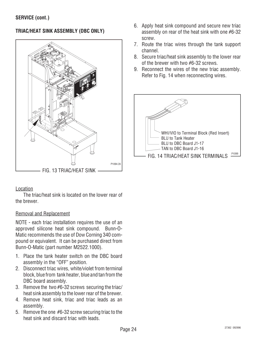
The Bunn System III is a versatile and efficient commercial brewing system designed for high-demand environments such as cafés, restaurants, and catering operations. Renowned for its reliability and performance, the System III combines advanced brewing technology with user-friendly features to deliver exceptional coffee consistently.One of the key features of the Bunn System III is its innovative brewing technology, which employs a unique infuser system. This design allows for optimal extraction of coffee flavors by ensuring that hot water is evenly distributed over the coffee grounds, maximizing flavor and ensuring a rich, balanced cup every time. The brewing system can brew up to 3.8 gallons of coffee per hour, making it an ideal choice for busy establishments.
The System III is equipped with an impressive built-in water heater that maintains a temperature of approximately 200°F, which is crucial for brewing coffee at the ideal temperature. This consistent temperature control minimizes the risk of under-extraction or over-extraction, resulting in better-tasting coffee. Additionally, the hot water faucet feature allows users to brew tea or instant beverages on demand, further enhancing the system's versatility.
Another characteristic that sets the Bunn System III apart is its user-friendly interface. The system is designed with intuitive controls, allowing baristas and kitchen staff to operate it with minimal training. The easy-to-read digital display provides critical information such as brew time and water temperature, ensuring that users can monitor the brewing process closely.
Durability is a hallmark of the Bunn System III. Constructed from high-quality materials, this brewing system is designed to withstand the rigors of commercial use. Its robust design ensures longevity and minimizes the need for frequent maintenance, making it a cost-effective choice for businesses.
The Bunn System III also features a large-capacity brew basket, capable of holding ample coffee grounds for high-volume brewing. This basket, combined with the system's efficient design, allows for quick and easy brewing, making it perfect for high traffic situations.
In conclusion, the Bunn System III coffee brewing system is a top choice for commercial coffee operations. Its advanced brewing technology, consistent temperature control, user-friendly features, and durable construction combine to create an exceptional brewing experience. Whether in a café, restaurant, or catering service, the Bunn System III stands out as an indispensable tool for delivering high-quality coffee efficiently.

