S.Installing Optional Controls (if applicable):

1.Install M&M 750P-MT-120 Probe Low Water Cut Off (LWCO)

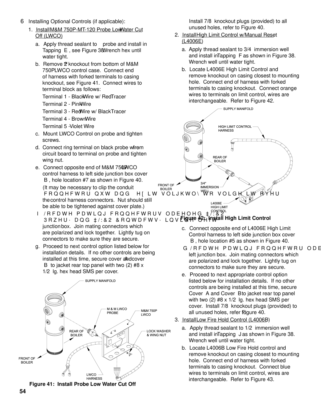
a.Apply thread sealant to ¾” probe and install in Tapping ‘E’, see Figure 38. Wrench hex until water tight.

b.Remove 2nd knockout from bottom of M&M 750P LWCO control case. Connect end

of harness with forked terminals to casing knockout, see Figure 41. Connect wires to terminal block as follows:

Terminal 1 - Black Wire w/ Red Tracer Terminal 2 - Pink Wire

Terminal 3 - Red Wire w/ Black Tracer Terminal 4 - Brown Wire

Terminal 5 - Violet Wire

c.Mount LWCO Control on probe and tighten screws.

d.Connect ring terminal on black probe wire from circuit board to terminal on probe and tighten wing nut.

e.Connect opposite end of M&M 750P LWCO control harness to left side junction box cover ‘B’, hole location #7 as shown in Figure 40.

(It may be necessary to clip the conduit connector nut and flex it slightly to slide it over the control harness connectors. Nut should still be able to be tightened against cover plate.)

f.Locate mating connectors labeled “LWCO Power” and “LWCO Contacts” inside left junction box. Join mating connectors which are polarized and lock together. Lightly tug on connectors to make sure they are secure.

g.Proceed to next control option listed below for installation details. If no other controls are being installed at this time, secure cover ‘A’ and cover ‘B’ to jacket rear top panel with two (2) #8 x 1/2” lg. hex head SMS per cover.

Figure 41: Install Probe Low Water Cut Off

Install 7/8” knockout plugs (provided) to all unused holes, refer to Figure 40.

2.Install High Limit Control w/Manual Reset (L4006E)

a.Apply thread sealant to 3/4” immersion well and install in Tapping ‘F’ as shown in Figure 38. Wrench well until water tight.

b.Locate L4006E High Limit Control and remove knockout on casing closest to mounting hole. Connect end of harness with forked terminals to casing knockout. Connect orange wires to terminals on limit control, wires are interchangeable. Refer to Figure 42.

Figure 42: Install High Limit Control

c.Connect opposite end of L4006E High Limit Control harness to left side junction box cover ‘B’, hole location #5 as shown in Figure 40.

d.Locate mating connector labeled “Limit” inside left junction box. Join mating connectors which are polarized and lock together. Lightly tug on connectors to make sure they are secure.

e.Proceed to next appropriate control option listed below for installation details. If no other controls are being installed at this time, secure Cover ‘A’ and Cover ‘B’ to jacket rear top panel with two (2) #8 x 1/2” lg. hex head SMS per cover. Install 7/8” knockout plugs (provided) to all unused holes, refer to Figure 40.

3.Install Low Fire Hold Control (L4006B)

a.Apply thread sealant to 1/2” immersion well and install in Tapping ‘J’ as shown in Figure 38. Wrench well until water tight.

b.Locate L4006B Low Fire Hold control and remove knockout on casing closest to mounting hole. Connect end of harness with forked terminals to casing knockout. Connect blue wires to terminals on limit control, wires are interchangeable. Refer to Figure 43.

54

Page 54
Image 54
Burnham FM01FD00B manual Install Probe Low Water Cut Off

FM01FD00B specifications

The Burnham FM01FD00B is a remarkable heating solution that combines efficiency, reliability, and advanced technology to meet the demands of modern homes and commercial spaces. Standing out in the crowded market of heating systems, the FM01FD00B is designed for those who prioritize both performance and energy savings.

One of the most significant features of the Burnham FM01FD00B is its advanced combustion technology. The system utilizes a high-efficiency burner that maximizes fuel usage, resulting in lower operating costs and reduced environmental impact. The unit is engineered to provide consistent heat distribution, ensuring that every corner of a room reaches a comfortable temperature quickly and effectively.

In addition to its efficient burning capabilities, the FM01FD00B is compatible with multiple heating mediums, allowing it to adapt to various fuel types, including natural gas and propane. This versatility makes it an excellent choice for homeowners looking for flexible heating options that can cater to their specific needs.

The FM01FD00B also comes equipped with a state-of-the-art control system that offers precise temperature management. Users can easily program their desired heating schedule, ensuring optimal comfort at all times. The intuitive interface allows for easy adjustments, making it simple to maintain a cozy environment whether at home or away.

Another key characteristic is the unit's robust construction. Built with high-quality materials, the Burnham FM01FD00B is designed to withstand harsh conditions and provide lasting performance. The durable exterior is resistant to corrosion, further enhancing its longevity and reliability.

Moreover, the system features built-in safety mechanisms that protect against overheating and other potential hazards, ensuring peace of mind for users. This focus on safety extends to its low emissions, making it an eco-friendly choice for those looking to reduce their carbon footprint.

In conclusion, the Burnham FM01FD00B is a high-efficiency heating solution that excels in performance, adaptability, and safety. Its advanced technologies, robust construction, and user-friendly features make it an ideal choice for anyone seeking a dependable and efficient heating system for their home or business. Whether you prioritize energy savings, reliability, or comfort, the FM01FD00B stands out as a top contender in the heating market.