Return Lever
The Return Lever (See Figure 3-1 [1]) on the top of the Coin Validator is operated by using the Vending Machine’s Return Button. Operating this lever is necessary if inserted coins are awaiting return, or a coin jam caused by stuck coins require removal. When the return lever is operated, the measurement and validation area of the Coin Vali- dator opens so that all objects within the Coin Validator are directed to the return area tray (See Figure 3-1 ).
Keyboard
The front of the Coin Validator is equipped with a five key touch-sensitive membrane Keyboard (See Figure 3-1 [4]) which allows filling of the Payout Unit's change tubes before the device is put into operation or emptying them for inventory (See section 4 "Functions" and section 7 "Operation" for further information).
Pilot Lights
There is a Pilot Light set of three Light-Emitting Diode (LED) at the front of the Coin Validator positioned beneath one another colored; Green, Yellow, and Red respectively (See Figure 3-1 [9]).
These LED Pilot Lights are mainly used for quick fault diagnosis, but can also indicate the units current status in normal operation conditions (See Figure 3-1 ).
If the top Green LED lights or flashes, no faults are indicated and the device is working properly. If the middle Yellow LED flashes there is a definite gen- eral fault indicated that usually can be easily reme- died.
If the bottom Red LED flashes, a fault that must be remedied by a service technician is indicated. (also see the section 14 "Trouble Shooting" appendix).
Interfaces
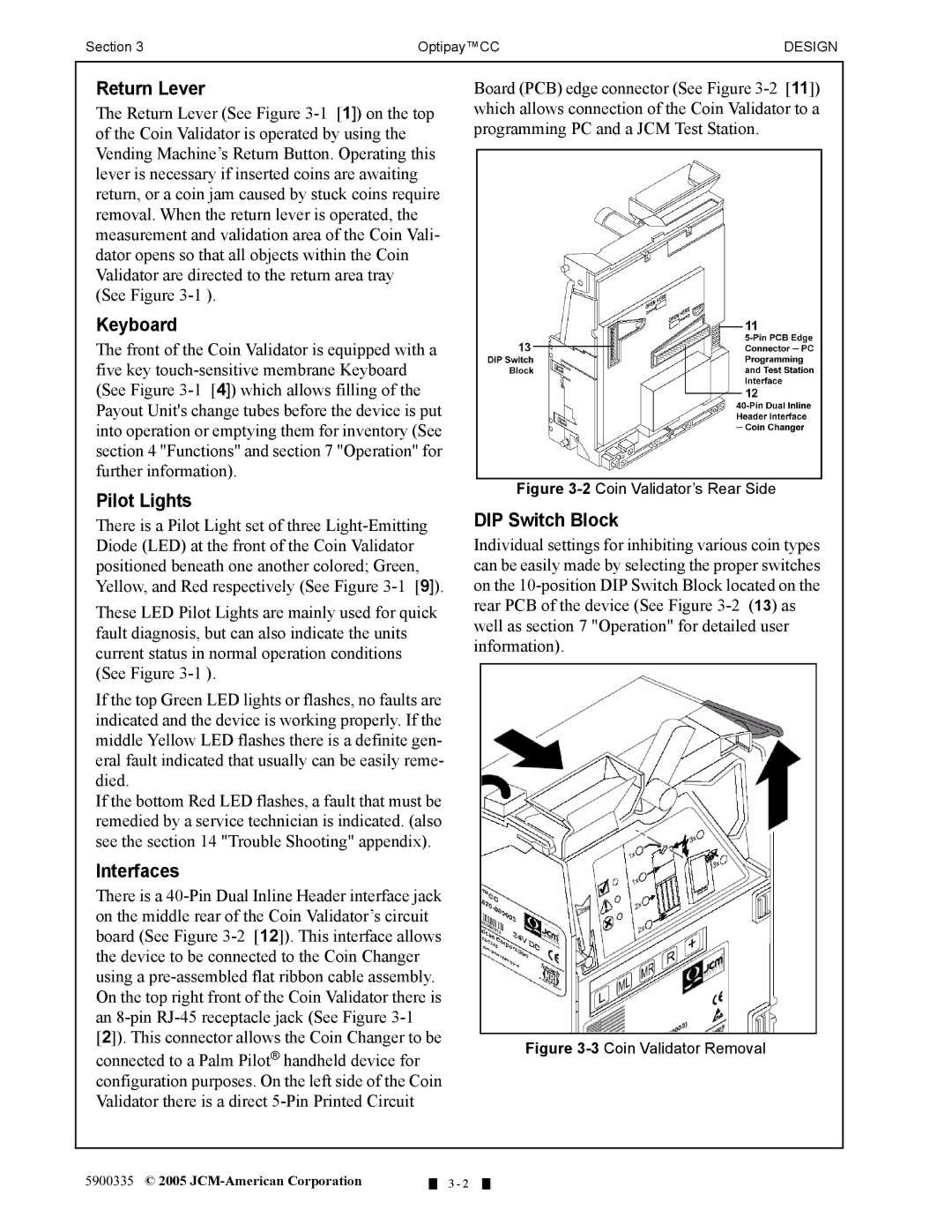
There is a 40-Pin Dual Inline Header interface jack on the middle rear of the Coin Validator’s circuit board (See Figure 3-2 [12]). This interface allows the device to be connected to the Coin Changer using a pre-assembled flat ribbon cable assembly. On the top right front of the Coin Validator there is an 8-pin RJ-45 receptacle jack (See Figure 3-1 [2]). This connector allows the Coin Changer to be
connected to a Palm Pilot® handheld device for configuration purposes. On the left side of the Coin Validator there is a direct 5-Pin Printed Circuit
Board (PCB) edge connector (See Figure 3-2 [11]) which allows connection of the Coin Validator to a programming PC and a JCM Test Station.
Figure 3-2Coin Validator’s Rear Side
DIP Switch Block
Individual settings for inhibiting various coin types can be easily made by selecting the proper switches on the 10-position DIP Switch Block located on the rear PCB of the device (See Figure 3-2 (13) as well as section 7 "Operation" for detailed user information).
Figure 3-3Coin Validator Removal

