Section 12 | Optipay™CC | PALM PILOT® USAGE |
a |
|
b |
|
c |
|
d |
|
e |
|
f |
|
g |
|
h |
|
j | i |
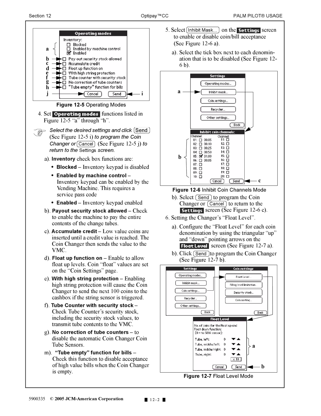
Figure 12-5 Operating Modes
4.Set  functions listed in Figure
 12-5 “a” through “h”.
Select the desired settings and click Send (See Figure
a). Inventory check box functions are:
•Blocked – Inventory keypad is disabled
•Enabled by machine control –
Inventory keypad can be enabled by the Vending Machine. This requires a service pass code
•Enabled – Inventory keypad enabled
b). Payout security stock allowed – Check to enable the machine to pay the entire contents of the change tubes.
c). Accumulate credit – Low value coins are inserted until a credit value is reached. The Coin Changer then sends the value to the VMC.
d). Float up function on – Enable to allow float up levels. Coin “float” values are set on the “Coin Settings” page.
e). With high string protection – Enabling high string protection will cause the Coin Changer to send the next 100 coins to the cashbox if the string sensor is triggered.
f). Tube Counter with security stock – Check Tube Counter’s security stock, including the security stock values, to transmit tube contents to the VMC.
g). No correction of tube counters – to disable the automatic Coin Changer Coin Tube Sensors.
m). “Tube empty” function for bills – Check this function to disable acceptance of high value bills when the Coin Changer is empty.
5.Select Inhibit Mask… on the ![]() screen to enable or disable coin/bill acceptance (See Figure
screen to enable or disable coin/bill acceptance (See Figure
a). Select the tick box next to each denomin- ation that is to be disabled (See Figure 12- 6 b).
a
b
c
Figure 12-6 Inhibit Coin Channels Mode
b). Select ![]() to program the Coin
to program the Coin
Changer or ![]() to return to the
to return to the
![]() screen (See Figure
screen (See Figure
a). Configure the “Float Level” for each coin denomination by using the triangular “up” and “down” pointing arrows on the ![]() screen (See Figure
screen (See Figure
b). Click ![]() to program the Coin Changer (See Figure
to program the Coin Changer (See Figure
![]() a
a
b
Figure 12-7 Float Level Mode
5900335 © 2005
1 2 - 2
