Unpacking and Installing Your
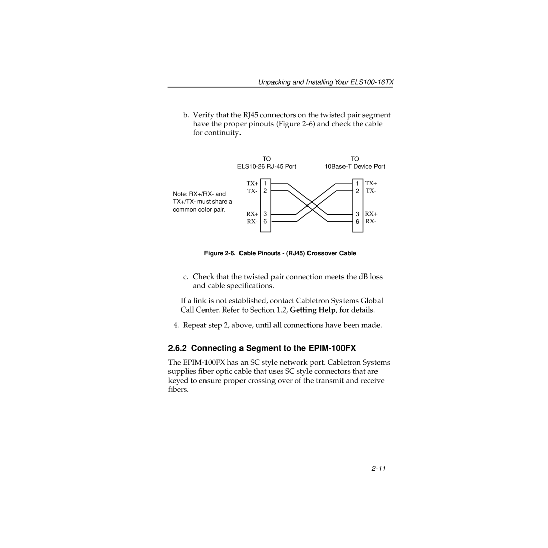
b.Verify that the RJ45 connectors on the twisted pair segment have the proper pinouts (Figure
|
| TO | TO |
| ||
| ||||||
|
|
|
|
|
| TX+ |
| TX+ | 1 |
|
| 1 | |
Note: RX+/RX- and | TX- | 2 |
|
| 2 | TX- |
|
|
|
|
|
| |
TX+/TX- must share a |
|
|
|
|
|
|
common color pair. | RX+ | 3 |
|
| 3 | RX+ |
|
|
| ||||
| RX- | 6 |
|
| 6 | RX- |
|
|
|
|
|
|
|
Figure 2-6. Cable Pinouts - (RJ45) Crossover Cable
c.Check that the twisted pair connection meets the dB loss and cable specifications.
If a link is not established, contact Cabletron Systems Global Call Center. Refer to Section 1.2, Getting Help, for details.
4. Repeat step 2, above, until all connections have been made.
2.6.2 Connecting a Segment to the EPIM-100FX
The