Technical Specifications
Table A-2. DB9 Pin Assignments
ELS100-16TX RJ45 (female) | DB9 pin (female) |
| | |
Pin 1 | (Rx) | Pin 2 |
| | |
Pin 4 | (Tx) | Pin 3 |
| | |
Pin 5 | (GND) | Pin 5 |
| | |
A.3 100BASE-T PIN ASSIGNMENTS
An Ethernet twisted-pair link segment requires two pairs of wires. Each wire pair is identified by solid and striped colored wires. For example, one wire in the pair might be red and the other wire, red with white stripes.
Connectors
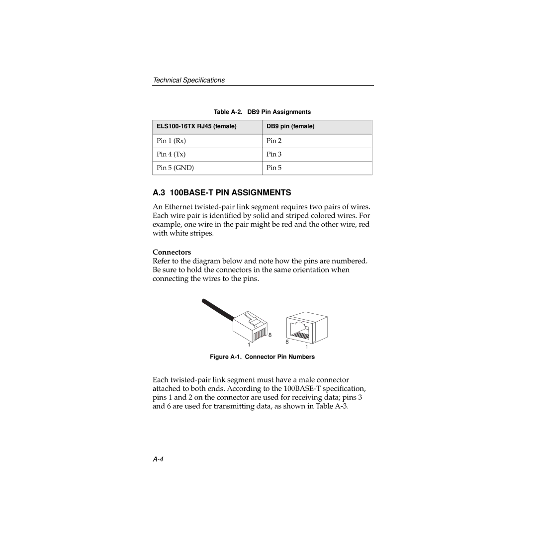
Refer to the diagram below and note how the pins are numbered. Be sure to hold the connectors in the same orientation when connecting the wires to the pins.
Figure A-1. Connector Pin Numbers
Each twisted-pair link segment must have a male connector attached to both ends. According to the 100BASE-T specification, pins 1 and 2 on the connector are used for receiving data; pins 3 and 6 are used for transmitting data, as shown in Table A-3.