Technical Specifications
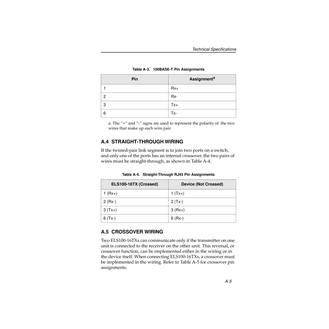
Table A-3. 100BASE-T Pin Assignments
Pin | Assignmenta |
1 | Rx+ |
| |
2 | Rx- |
| |
3 | Tx+ |
| |
6 | Tx- |
| |
a. The “+” and “-” signs are used to represent the polarity of the two wires that make up each wire pair.
A.4 STRAIGHT-THROUGH WIRING
If the twisted-pair link segment is to join two ports on a switch, and only one of the ports has an internal crossover, the two pairs of wires must be straight-through, as shown in Table A-4.
Table A-4. Straight-Through RJ45 Pin Assignments
| ELS100-16TX (Crossed) | | Device (Not Crossed) |
| | | |
1 | (Rx+) | 1 | (Tx+) |
| | | |
2 | (Rx-) | 2 | (Tx-) |
| | | |
3 | (Tx+) | 3 | (Rx+) |
| | | |
6 | (Tx-) | 6 | (Rx-) |
| | | |
A.5 CROSSOVER WIRING
Two ELS100-16TXs can communicate only if the transmitter on one unit is connected to the receiver on the other unit. This reversal, or crossover function, can be implemented either in the wiring or in the device itself. When connecting ELS100-16TXs, a crossover must be implemented in the wiring. Refer to Table A-5 for crossover pin assignments.