Cabletron Systems FDDI INSTALLING/REMOVING THE 7F06-02 MODULE, Installing in the 7C03 SmartSwitch

Models: FDDI

1 32
Download 32 pages 27.98 Kb
Page 21
Image 21
3.3INSTALLING/REMOVING THE 7F06-02 MODULE

Chapter 3: Installation/Removal

3.3INSTALLING/REMOVING THE 7F06-02 MODULE

The following procedure details the installation and removal procedure for the 7F06-02 module.

3.3.1Installing in the 7C03 SmartSwitch

The 7F06-02 Module is installed in the 7C03 MMAC SmartSwitch using the following steps and referring to Figure 3-2.

Note: The left-most slot in the 7C03 MMAC SmartSwitch is reserved for the 7X00 SmartSwitch Module.

Note: Before installing the 7F06-02 module, attach the antistatic wrist strap included with the SmartSwitch or SmartSwitch module by following the instructions printed on the package.

1.As a precaution, power down the MMAC 8 before beginning the installation or removal of any modules. At the very minimum, the 7C03 must be pulled to disconnect it from the power source. Damage to modules may result if this procedure is not followed.

2.Remove the blank panel covering the slot in which the module will be installed. All other slots must remain covered to ensure proper airflow and cooling.

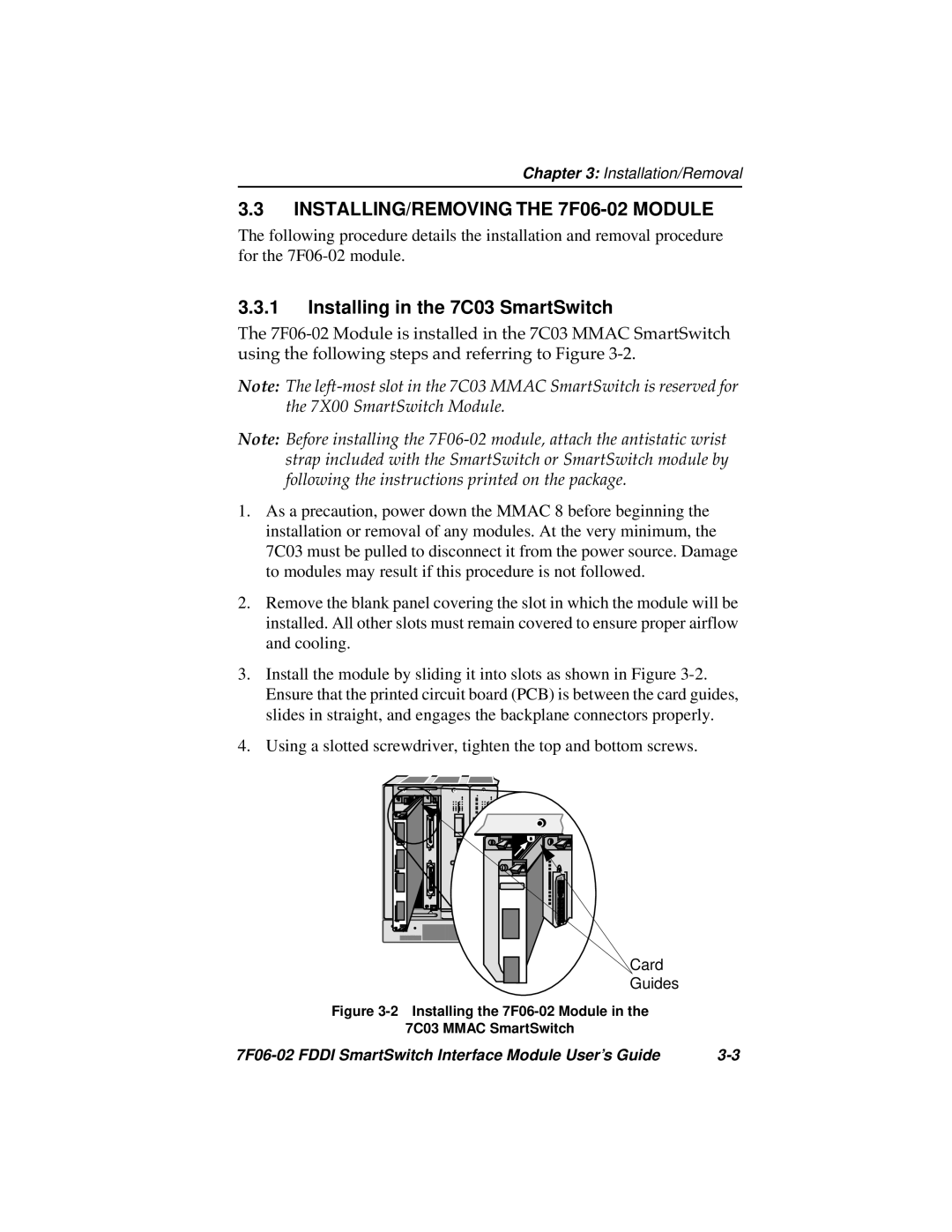
3.Install the module by sliding it into slots as shown in Figure 3-2. Ensure that the printed circuit board (PCB) is between the card guides, slides in straight, and engages the backplane connectors properly.

4.Using a slotted screwdriver, tighten the top and bottom screws.

Card

Guides

Figure 3-2 Installing the 7F06-02 Module in the

7C03 MMAC SmartSwitch

7F06-02 FDDI SmartSwitch Interface Module User’s Guide

3-3

Page 21
Image 21
Cabletron Systems FDDI manual INSTALLING/REMOVING THE 7F06-02 MODULE, Installing in the 7C03 SmartSwitch