Chapter 3: Installation/Removal
3.3.4Removing the
The
Workgroup SmartSwitch, can be removed whenever necessary. Follow the steps below and refer to Figures
Note: Before removing the
1.As a precaution, power down the MMAC 8 before beginning the installation or removal of any modules. At the very minimum the 7C04 or
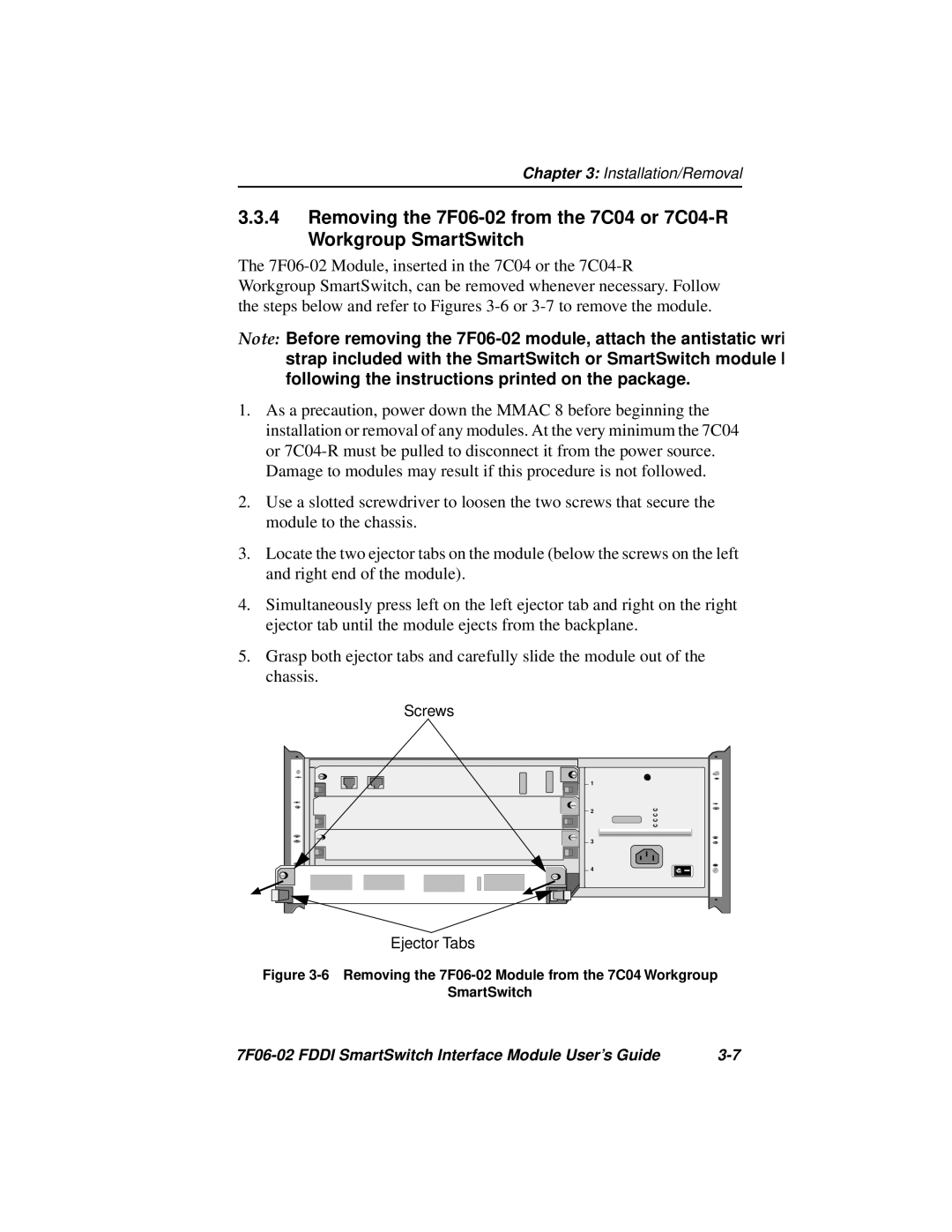
2.Use a slotted screwdriver to loosen the two screws that secure the module to the chassis.
3.Locate the two ejector tabs on the module (below the screws on the left and right end of the module).
4.Simultaneously press left on the left ejector tab and right on the right ejector tab until the module ejects from the backplane.
5.Grasp both ejector tabs and carefully slide the module out of the chassis.
Screws
1 |
2 |
3 |
4 |
Ejector Tabs
Figure 3-6 Removing the 7F06-02 Module from the 7C04 Workgroup
SmartSwitch
|