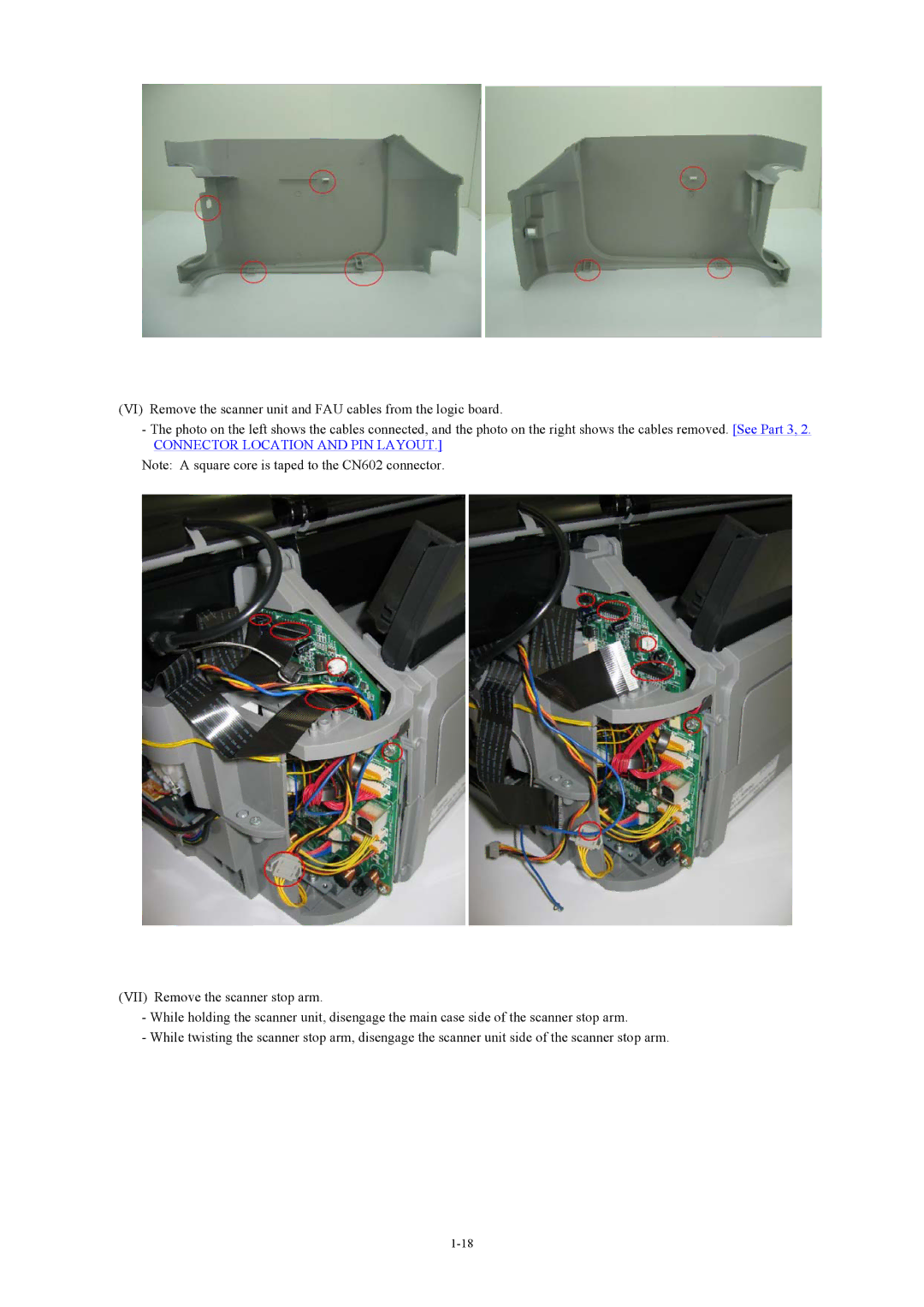
(VI) Remove the scanner unit and FAU cables from the logic board.
-The photo on the left shows the cables connected, and the photo on the right shows the cables removed. [See Part 3, 2.
CONNECTOR LOCATION AND PIN LAYOUT.]
Note: A square core is taped to the CN602 connector.
(VII) Remove the scanner stop arm.
-While holding the scanner unit, disengage the main case side of the scanner stop arm.
-While twisting the scanner stop arm, disengage the scanner unit side of the scanner stop arm.