UNIT | MAXIMUM SHIPPING WEIGHT | |
48HJ | Lb | Kg |
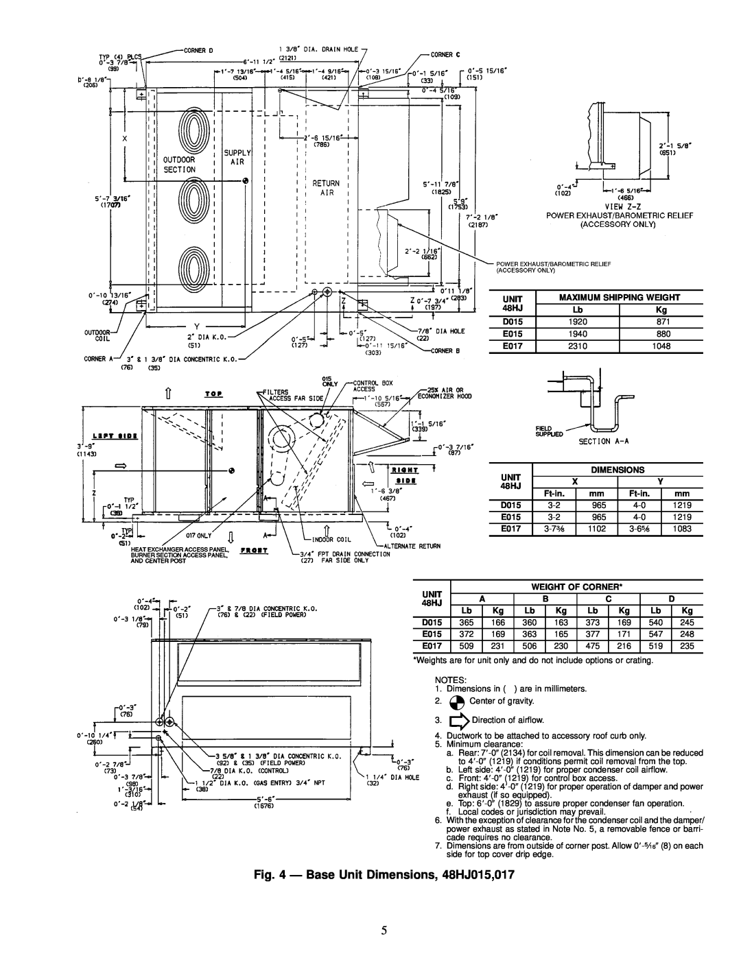
D015 | 1920 | 871 |
E015 | 1940 | 880 |
E017 | 2310 | 1048 |
|
|
|
|
| UNIT |
|
|
|
|
| DIMENSIONS |
|
|
|
| |||||
|
|
|
|
|
|
|
| X |
|
|
|
|
| Y |
|
| ||||
|
|
|
|
| 48HJ |
|
|
|
|
|
|
|
|
|
| |||||
|
|
|
|
|
|
|
|
|
| mm |
|
|
| mm | ||||||
|
|
|
|
| D015 |
|
|
| 965 |
|
|
|
| 1219 | ||||||
|
|
|
|
| E015 |
|
|
| 965 |
|
|
|
| 1219 | ||||||
|
|
|
|
| E017 |
|
|
| 1102 |
|
|
| 1083 | |||||||
|
|
|
|
|
|
|
|
|
|
|
|
|
|
|
| |||||
UNIT |
|
|
|
|
|
| WEIGHT OF CORNER* |
|
|
|
| |||||||||
|
| A |
|
|
| B |
| C |
|
|
|
|
| D | ||||||
48HJ |
|
|
|
|
|
|
|
|
|
|
| |||||||||
|
| Lb |
|
| Kg |
| Lb |
| Kg |
| Lb |
|
| Kg |
| Lb |
| Kg | ||
D015 |
| 365 |
| 166 |
| 360 |
| 163 |
| 373 |
| 169 |
| 540 |
| 245 | ||||
E015 |
| 372 |
| 169 |
| 363 |
| 165 |
| 377 |
| 171 |
| 547 |
| 248 | ||||
E017 |
| 509 |
| 231 |
| 506 |
| 230 |
| 475 |
| 216 |
| 519 |
| 235 | ||||
|
|
|
|
|
|
|
|
|
| |||||||||||
*Weights are for unit only and do not include options or crating. |
|
| ||||||||||||||||||
NOTES: |
|
|
|
|
|
|
|
|
|
|
|
|
|
|
|
|
|
| ||
1. | Dimensions in ( ) are in millimeters. |
|
|
|
|
|
|
| ||||||||||||
2.![]() Center of gravity.
Center of gravity.
3.![]() Direction of air¯ow.
Direction of air¯ow.
4.Ductwork to be attached to accessory roof curb only.
5.Minimum clearance:
a.Rear: 7
b.Left side: 4
c.Front: 4
d.Right side: 4
e.Top: 6
f.Local codes or jurisdiction may prevail.
6.With the exception of clearance for the condenser coil and the damper/ power exhaust as stated in Note No. 5, a removable fence or barri- cade requires no clearance.
7.Dimensions are from outside of corner post. Allow 0
Fig. 4 Ð Base Unit Dimensions, 48HJ015,017
5