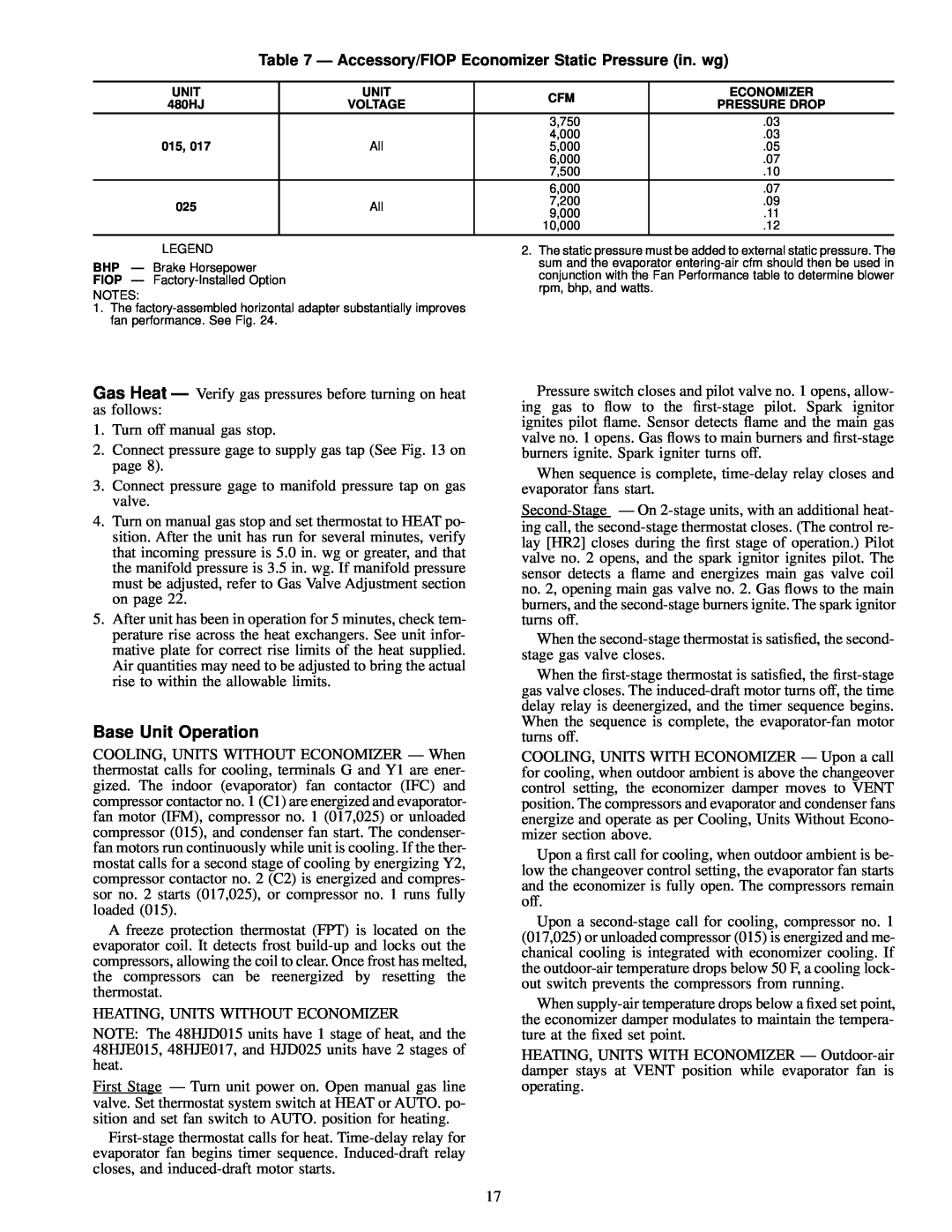
Table 7 Ð Accessory/FIOP Economizer Static Pressure (in. wg)
UNIT | UNIT | CFM | ECONOMIZER | |
480HJ | VOLTAGE | PRESSURE DROP | ||
| ||||
|
| 3,750 | .03 | |
015, 017 |
| 4,000 | .03 | |
All | 5,000 | .05 | ||
|
| 6,000 | .07 | |
|
| 7,500 | .10 | |
|
| 6,000 | .07 | |
025 | All | 7,200 | .09 | |
9,000 | .11 | |||
|
| |||
|
| 10,000 | .12 | |
|
|
|
|
LEGEND
BHP Ð Brake Horsepower
FIOP Ð
NOTES:
1.The
2.The static pressure must be added to external static pressure. The sum and the evaporator
Gas Heat Ð Verify gas pressures before turning on heat as follows:
1.Turn off manual gas stop.
2.Connect pressure gage to supply gas tap (See Fig. 13 on page 8).
3.Connect pressure gage to manifold pressure tap on gas valve.
4.Turn on manual gas stop and set thermostat to HEAT po- sition. After the unit has run for several minutes, verify that incoming pressure is 5.0 in. wg or greater, and that the manifold pressure is 3.5 in. wg. If manifold pressure must be adjusted, refer to Gas Valve Adjustment section on page 22.
5.After unit has been in operation for 5 minutes, check tem- perature rise across the heat exchangers. See unit infor- mative plate for correct rise limits of the heat supplied. Air quantities may need to be adjusted to bring the actual rise to within the allowable limits.
Base Unit Operation
COOLING, UNITS WITHOUT ECONOMIZER Ð When thermostat calls for cooling, terminals G and Y1 are ener- gized. The indoor (evaporator) fan contactor (IFC) and compressor contactor no. 1 (C1) are energized and evaporator- fan motor (IFM), compressor no. 1 (017,025) or unloaded compressor (015), and condenser fan start. The condenser- fan motors run continuously while unit is cooling. If the ther- mostat calls for a second stage of cooling by energizing Y2, compressor contactor no. 2 (C2) is energized and compres- sor no. 2 starts (017,025), or compressor no. 1 runs fully loaded (015).
A freeze protection thermostat (FPT) is located on the evaporator coil. It detects frost
HEATING, UNITS WITHOUT ECONOMIZER
NOTE: The 48HJD015 units have 1 stage of heat, and the 48HJE015, 48HJE017, and HJD025 units have 2 stages of heat.
First Stage Ð Turn unit power on. Open manual gas line valve. Set thermostat system switch at HEAT or AUTO. po- sition and set fan switch to AUTO. position for heating.
Pressure switch closes and pilot valve no. 1 opens, allow- ing gas to ¯ow to the
When sequence is complete,
When the
When the
COOLING, UNITS WITH ECONOMIZER Ð Upon a call for cooling, when outdoor ambient is above the changeover control setting, the economizer damper moves to VENT position. The compressors and evaporator and condenser fans energize and operate as per Cooling, Units Without Econo- mizer section above.
Upon a ®rst call for cooling, when outdoor ambient is be- low the changeover control setting, the evaporator fan starts and the economizer is fully open. The compressors remain off.
Upon a
When
HEATING, UNITS WITH ECONOMIZER Ð
17