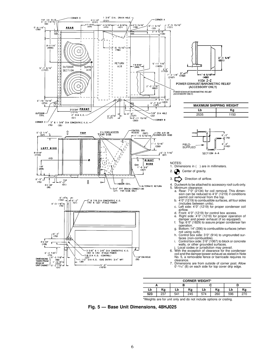
48HJ015-025 specifications
The Carrier 48HJ015-025 is a distinguished series of rooftop packaged units renowned for their efficient performance and reliability in light commercial applications. Designed for a variety of indoor environments, these units are engineered to provide efficient heating and cooling solutions, making them suitable for retail spaces, offices, and other commercial buildings.One of the main features of the Carrier 48HJ series is its advanced scroll compressor technology, which enhances the overall efficiency of the systems. This type of compressor is known for its durability and quiet operation, providing consistent temperature control while minimizing energy consumption. The use of a scroll compressor contributes to a higher Seasonal Energy Efficiency Ratio (SEER) and Heating Seasonal Performance Factor (HSPF), making these units a smart choice for energy-conscious businesses.
Additionally, the 48HJ series incorporates a multi-speed indoor blower that allows for precise airflow control. This feature ensures optimal indoor comfort by adjusting the air distribution based on the specific heating or cooling needs of the space. The ability to adapt to varying load conditions enhances efficiency and reduces energy wastage.
Another noteworthy characteristic of the Carrier 48HJ015-025 is its robust construction. Built with galvanized steel, the units are designed to withstand harsh environmental conditions, ensuring longevity and minimal maintenance requirements. The powder-painted finish offers corrosion resistance, contributing to the unit’s durability over time.
The series also integrates advanced controls for ease of operation. The user-friendly thermostat enables precise temperature management and can be programmed according to the specific needs of the facility. Moreover, compatibility with Building Management Systems (BMS) facilitates seamless integration into existing infrastructure, enabling remote monitoring and enhanced operational efficiency.
In terms of environmental considerations, the Carrier 48HJ series utilizes R-410A refrigerant, which is known for its reduced impact on the ozone layer compared to older refrigerants. This commitment to sustainability aligns with modern environmental standards and regulations.
Overall, the Carrier 48HJ015-025 stands out as a versatile and efficient rooftop packaged unit, perfect for varying commercial applications. Its combination of advanced technology, reliability, and user-focused design makes it a prominent choice for businesses seeking optimized climate control solutions while ensuring sustainability and energy efficiency.

