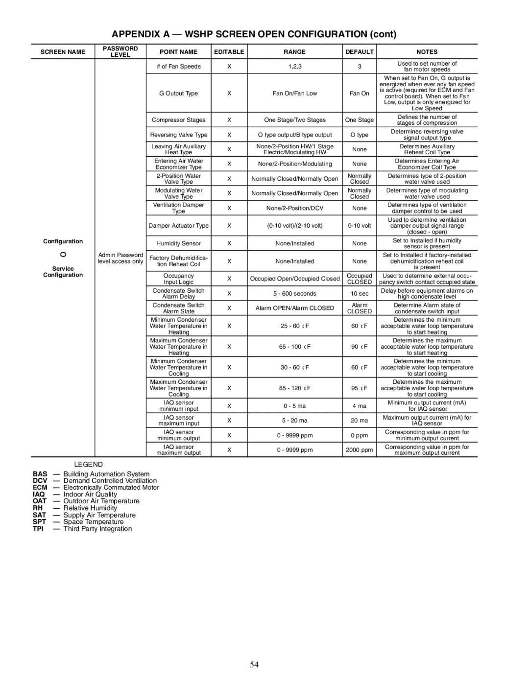
APPENDIX A — WSHP SCREEN OPEN CONFIGURATION (cont)
SCREEN NAME
Configuration
→
Service
Configuration
PASSWORD | POINT NAME | EDITABLE | RANGE | DEFAULT | NOTES | |
LEVEL | ||||||
|
|
|
|
| ||
| # of Fan Speeds | X | 1,2,3 | 3 | Used to set number of | |
| fan motor speeds | |||||
|
|
|
|
| ||
|
|
|
|
| When set to Fan On, G output is | |
|
|
|
|
| energized when ever any fan speed | |
| G Output Type | X | Fan On/Fan Low | Fan On | is active (required for ECM and Fan | |
| control board). When set to Fan | |||||
|
|
|
|
| ||
|
|
|
|
| Low, output is only energized for | |
|
|
|
|
| Low Speed | |
| Compressor Stages | X | One Stage/Two Stages | One Stage | Defines the number of | |
| stages of compression | |||||
|
|
|
|
| ||
| Reversing Valve Type | X | O type output/B type output | O type | Determines reversing valve | |
| signal output type | |||||
|
|
|
|
| ||
| Leaving Air Auxiliary | X | None | Determines Auxiliary | ||
| Heat Type | Electric/Modulating HW | Reheat Coil Type | |||
|
|
| ||||
| Entering Air Water | X | None | Determines Entering Air | ||
| Economizer Type | Economizer Coil Type | ||||
|
|
|
| |||
| X | Normally Closed/Normally Open | Normally | Determines type of | ||
| Valve Type | Closed | water valve used | |||
|
|
| ||||
| Modulating Water | X | Normally Closed/Normally Open | Normally | Determines type of modulating | |
| Valve Type | Closed | water valve used | |||
|
|
| ||||
| Ventilation Damper | X | None | Determines type of ventilation | ||
| Type | damper control to be used | ||||
|
|
|
| |||
|
|
|
|
| Used to determine ventilation | |
| Damper Actuator Type | X | damper output signal range | |||
|
|
|
|
| (closed - open) | |
| Humidity Sensor | X | None/Installed | None | Set to Installed if humidity | |
| sensor is present | |||||
|
|
|
|
| ||
Admin Password | Factory Dehumidifica- | X | None/Installed | None | Set to Installed if | |
level access only | tion Reheat Coil | dehumidification reheat coil | ||||
|
|
|
| is present | ||
|
|
|
|
| ||
| Occupancy | X | Occupied Open/Occupied Closed | Occupied | Used to determine external occu- | |
| Input Logic | CLOSED | pancy switch contact occupied state | |||
|
|
| ||||
| Condensate Switch | X | 5 - 600 seconds | 10 sec | Delay before equipment alarms on | |
| Alarm Delay | high condensate level | ||||
|
|
|
| |||
| Condensate Switch | X | Alarm OPEN/Alarm CLOSED | Alarm | Determine Alarm state of | |
| Alarm State | CLOSED | condensate switch input | |||
|
|
| ||||
| Minimum Condenser |
| 25 - 60 ° F | 60 ° F | Determines the minimum | |
| Water Temperature in | X | acceptable water loop temperature | |||
| Heating |
|
|
| to start heating | |
| Maximum Condenser |
| 65 - 100 ° F | 90 ° F | Determines the maximum | |
| Water Temperature in | X | acceptable water loop temperature | |||
| Heating |
|
|
| to start heating | |
| Minimum Condenser |
| 30 - 60 ° F | 60 ° F | Determines the minimum | |
| Water Temperature in | X | acceptable water loop temperature | |||
| Cooling |
|
|
| to start cooling | |
| Maximum Condenser |
| 85 - 120 ° F | 95 ° F | Determines the maximum | |
| Water Temperature in | X | acceptable water loop temperature | |||
| Cooling |
|
|
| to start cooling | |
| IAQ sensor | X | 0 - 5 ma | 4 ma | Minimum output current (mA) | |
| minimum input | for IAQ sensor | ||||
|
|
|
| |||
| IAQ sensor | X | 5 - 20 ma | 20 ma | Maximum output current (mA) for | |
| maximum input | IAQ sensor | ||||
|
|
|
| |||
| IAQ sensor | X | 0 - 9999 ppm | 0 ppm | Corresponding value in ppm for | |
| minimum output | minimum output current | ||||
|
|
|
| |||
| IAQ sensor | X | 0 - 9999 ppm | 2000 ppm | Corresponding value in ppm for | |
| maximum output | maximum output current | ||||
|
|
|
|
| LEGEND |
BAS | — Building Automation System |
DCV | — Demand Controlled Ventilation |
ECM | — Electronically Commutated Motor |
IAQ | — Indoor Air Quality |
OAT | — Outdoor Air Temperature |
RH | — Relative Humidity |
SAT | — Supply Air Temperature |
SPT | — Space Temperature |
TPI | — Third Party Integration |
54