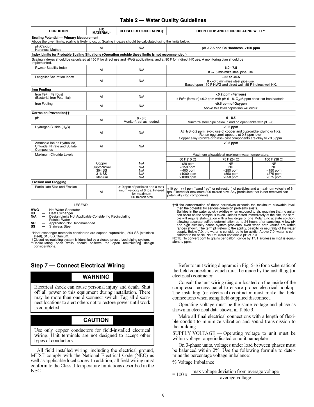
Table 2 — Water Quality Guidelines
CONDITION | HX | CLOSED RECIRCULATING† |
| OPEN LOOP AND RECIRCULATING WELL** | ||||
MATERIAL* |
| |||||||
|
|
|
|
|
|
| ||
Scaling Potential — Primary Measurement |
|
|
|
|
|
| ||
Above the given limits, scaling is likely to occur. Scaling indexes should be calculated using the limits below. |
|
|
|
| ||||
pH/Calcium | All | N/A |
| pH < 7.5 and Ca Hardness, <100 ppm |
| |||
Hardness Method |
|
| ||||||
|
|
|
|
|
|
| ||
Index Limits for Probable Scaling Situations (Operation outside these limits is not recommended.) |
|
|
|
| ||||
Scaling indexes should be calculated at 150 F for direct use and HWG applications, and at 90 F for indirect HX use. A monitoring plan should be |
| |||||||
implemented. |
|
|
|
|
|
|
| |
Ryznar Stability Index | All | N/A |
| 6.0 - 7.5 |
|
| ||
|
| If >7.5 minimize steel pipe use. |
| |||||
|
|
|
|
| ||||
Langelier Saturation Index |
|
|
|
|
| |||
| All | N/A |
| If |
| |||
|
|
| Based upon 150 F HWG and direct well, 85 F indirect well HX. | |||||
Iron Fouling |
|
|
|
|
|
|
| |
Iron Fe2+ (Ferrous) | All | N/A |
|
| <0.2 ppm (Ferrous) |
| ||
(Bacterial Iron Potential) | If Fe2+ (ferrous) >0.2 ppm with pH 6 - 8, O2<5 ppm check for iron bacteria. | |||||||
|
| |||||||
Iron Fouling | All | N/A |
|
| <0.5 ppm of Oxygen |
| ||
|
| Above this level deposition will occur. |
| |||||
|
|
|
|
| ||||
Corrosion Prevention†† |
|
|
|
|
|
|
| |
pH | All | 6 - 8.5 |
| 6 - 8.5 |
|
| ||
| Monitor/treat as needed. | Minimize steel pipe below 7 and no open tanks with pH <8. | ||||||
|
| |||||||
Hydrogen Sulfide (H2S) |
|
|
|
| <0.5 ppm |
| ||
| All | N/A | At H2S>0.2 ppm, avoid use of copper and cupronickel piping or HXs. | |||||
|
|
|
| Rotten egg smell appears at 0.5 ppm level. |
| |||
|
|
| Copper alloy (bronze or brass) cast components are okay to <0.5 ppm. | |||||
Ammonia Ion as Hydroxide, |
|
|
|
| <0.5 ppm |
| ||
Chloride, Nitrate and Sulfate | All | N/A |
|
|
|
|
| |
Compounds |
|
|
|
|
|
|
| |
Maximum Chloride Levels |
|
| Maximum allowable at maximum water temperature. | |||||
|
|
| 50 F (10 C) |
| 75 F (24 C) |
| 100 F (38 C) | |
| Copper | N/A | <20 ppm |
| NR |
| NR | |
| CuproNickel | N/A | <150 ppm |
| NR |
| NR | |
| 304 SS | N/A | <400 ppm |
| <250 ppm |
| <150 ppm | |
| 316 SS | N/A | <1000 ppm |
| <550 ppm |
| <375 ppm | |
| Titanium | N/A | >1000 ppm |
| >550 ppm |
| >375 ppm | |
Erosion and Clogging
Particulate Size and Erosion |
| <10 ppm of particles and a max- | <10 ppm (<1 ppm “sand free” for reinjection) of particles and a maximum velocity of 6 |
| All | imum velocity of 6 fps. Filtered | fps. Filtered for maximum 800 micron size. Any particulate that is not removed can |
|
| for maximum | potentially clog components. |
|
| 800 micron size. | |
|
|
|
LEGEND
HWG — Hot Water Generator
HX — Heat Exchanger
N/A — Design Limits Not Applicable Considering Recirculating
Potable Water
NR — Application Not Recommended
SS— Stainless Steel
*Heat exchanger materials considered are copper, cupronickel, 304 SS (stainless steel), 316 SS, titanium.
†Closed recirculating system is identified by a closed pressurized piping system. **Recirculating open wells should observe the open recirculating design
considerations.
††If the concentration of these corrosives exceeds the maximum allowable level, then the potential for serious corrosion problems exists.
Sulfides in the water quickly oxidize when exposed to air, requiring that no agita- tion occur as the sample is taken. Unless tested immediately at the site, the sam- ple will require stabilization with a few drops of one Molar zinc acetate solution, allowing accurate sulfide determination up to 24 hours after sampling. A low pH and high alkalinity cause system problems, even when both values are within ranges shown. The term pH refers to the acidity, basicity, or neutrality of the water supply. Below 7.0, the water is considered to be acidic. Above 7.0, water is con- sidered to be basic. Neutral water contains a pH of 7.0.
NOTE: To convert ppm to grains per gallon, divide by 17. Hardness in mg/l is equiv- alent to ppm.
Step 7 — Connect Electrical Wiring
![]() WARNING
WARNING
Electrical shock can cause personal injury and death. Shut off all power to this equipment during installation. There may be more than one disconnect switch. Tag all discon- nect locations to alert others not to restore power until work is completed.
![]() CAUTION
CAUTION
Use only copper conductors for
All field installed wiring, including the electrical ground, MUST comply with the National Electrical Code (NEC) as well as applicable local codes. In addition, all field wiring must conform to the Class II temperature limitations described in the NEC.
Refer to unit wiring diagrams in Fig.
Consult the unit wiring diagram located on the inside of the compressor access panel to ensure proper electrical hookup. The installing (or electrical) contractor must make the field connections when using
Operating voltage must be the same voltage and phase as shown in electrical data shown in Table 3.
Make all final electrical connections with a length of flexi- ble conduit to minimize vibration and sound transmission to the building.
SUPPLY VOLTAGE — Operating voltage to unit must be within voltage range indicated on unit nameplate.
On
% Voltage Imbalance
= 100 x | max voltage deviation from average voltage |
| average voltage |
9