Step 8 — Connect Low Voltage Wiring
THERMOSTAT CONNECTIONS — The thermostat should be wired directly to the Aquazone™ control board. See Fig.
WATER FREEZE PROTECTION — The Aquazone control allows the field selection of source fluid freeze protection points through jumpers. The factory setting of jumper JW3 (FP1) is set for water at 30 F. In earth loop applications, jumper JW3 should be clipped to change the setting to 13 F when using antifreeze in colder earth loop applications. See Fig. 20.
AIR COIL FREEZE PROTECTION — The air coil freeze protection jumper JW2 (FP2) is factory set for 30 F and should not need adjusting, unless using
THERMOSTAT
| Y1 |
|
|
Y2 | |
Reversing Valve | O |
Fan | G |
24Vac Hot | R |
|
|
24Vac Com | C |
|
|
| AL |
|
|
CompleteC 1 CompleteC 2
Y |
| Y |
|
|
|
|
|
|
O |
| O |
G |
| G |
|
|
|
R |
| R |
CC
ALAL
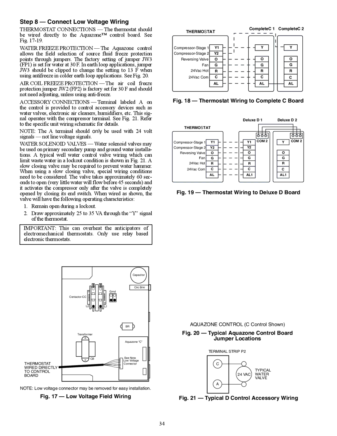
ACCESSORY CONNECTIONS — Terminal labeled A on the control is provided to control accessory devices such as water valves, electronic air cleaners, humidifiers, etc. This sig- nal operates with the compressor terminal. See Fig. 21. Refer
Fig. 18 — Thermostat Wiring to Complete C Board
to the specific unit wiring schematic for details.
NOTE: The A terminal should only be used with 24 volt signals — not line voltage signals.
WATER SOLENOID VALVES — Water solenoid valves may be used on primary secondary pump and ground water installa- tions. A typical well water control valve wiring which can limit waste water in a lockout condition is shown in Fig. 21. A slow closing valve may be required to prevent water hammer. When using a slow closing valve, special wiring conditions need to be considered. The valve takes approximately 60 sec- onds to open (very little water will flow before 45 seconds) and it activates the compressor only after the valve is completely
THERMOSTAT
Y1 | |
Y2 | |
Reversing Valve | O |
Fan | G |
24Vac Hot | R |
|
|
24Vac Com | C |
|
|
| AL |
|
|
Deluxe D 1 | Deluxe D 2 |
Y1 COM 2 | Y COM 2 |
Y2 |
|
O | O |
G | G |
R | R |
CC
AL1AL1
opened by closing its end switch. When wired as shown, the valve will have the following operating characteristics:
1.Remain open during a lockout.
2.Draw approximately 25 to 35 VA through the “Y” signal of the thermostat.
IMPORTANT: This can overheat the anticipators of electromechanical thermostats. Only use relay based electronic thermostats.
| Capacitor |
| Circ Brkr |
| Grnd |
| |
L2 | L1 |
| BR |
Transformer |
|
| Aquazone “C” |
CB | See Note |
THERMOSTAT | Low Voltage |
Connector | |
WIRED DIRECTLY |
|
TO CONTROL |
|
BOARD |
|
NOTE: Low voltage connector may be removed for easy installation.
Fig. 17 — Low Voltage Field Wiring
34
Fig. 19 — Thermostat Wiring to Deluxe D Board
AQUAZONE CONTROL (C Control Shown)
Fig. 20 — Typical Aquazone Control Board
Jumper Locations
TERMINAL STRIP P2
C
TYPICAL 24 VAC WATER
VALVE
A