BC | — Blower Contactor |
CB | — Circuit Breaker |
CC— Compressor Contactor
CO | — Sensor, Condensate Overflow |
ECR | — Enthalpy Control Relay |
FP1 | — Sensor, Water Coil Freeze Protection |
FP2 | — Sensor, Air Coil Freeze Protection |
GFI | — Ground Fault Interrupter |
HP | — |
HPWR | — High Pressure Water Relay |
HPWS | — High Pressure Water Switch |
JW3 | — Clippable Field Selection Jumper |
LAR | — Low Ambient Relay |
LOC | — Loss of Charge Pressure Switch |
MAR | — Mixed Air Relay |
MO | — Motorized Outside Air Damper |
MV | — Motorized Valve |
OAT | — Outdoor Air Thermostat |
PDB | — Power Distribution Block |
RVS | — Reversing Valve Solenoid |
TRANS — Transformer
Factory Line Voltage Wiring
Factory Low Voltage Wiring
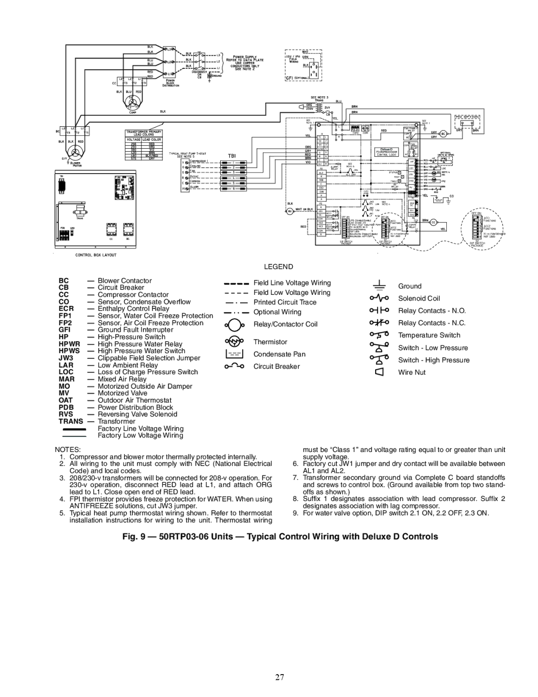
LEGEND
Field Line Voltage Wiring
Field Low Voltage Wiring
Printed Circuit Trace
Optional Wiring
Relay/Contactor Coil
Thermistor
Condensate Pan
Circuit Breaker
Deluxe D
a50-8556
Ground
Solenoid Coil
Relay Contacts - N.O.
Relay Contacts - N.C.
Temperature Switch
Switch - Low Pressure
Switch - High Pressure
Wire Nut
NOTES:
1.Compressor and blower motor thermally protected internally.
2.All wiring to the unit must comply with NEC (National Electrical Code) and local codes.
3.
4.FPI thermistor provides freeze protection for WATER. When using ANTIFREEZE solutions, cut JW3 jumper.
5.Typical heat pump thermostat wiring shown. Refer to thermostat installation instructions for wiring to the unit. Thermostat wiring
must be “Class 1” and voltage rating equal to or greater than unit supply voltage.
6.Factory cut JW1 jumper and dry contact will be available between AL1 and AL2.
7.Transformer secondary ground via Complete C board standoffs and screws to control box. (Ground available from top two stand- offs as shown.)
8.Suffix 1 designates association with lead compressor. Suffix 2 designates association with lag compressor.
9.For water valve option, DIP switch 2.1 ON, 2.2 OFF, 2.3 ON.
Fig. 9 — 50RTP03-06 Units — Typical Control Wiring with Deluxe D Controls
27