ACCESSORIES
1.Electronic Air Cleaner (EAC)
Connect an accessory Electronic Air Cleaner (if used) us- ing
2.Humidifier (HUM)
Connect an accessory 24 VAC, 0.5 amp. maximum hu- midifier (if used) to the
NOTE: A
NOTE: DO NOT connect furnace control HUM terminal to HUM (humidifier) terminal on Thermidistat, Zone Controller or similar device. See Thermidistatt, Zone Controller, thermostat, or controller manufacturer’s instructions for proper connection.
VENTING
The furnace shall be connected to a listed factory built chimney or vent or a
SETUP SWITCHES | TWINNING AND/OR |
COMPONENT TEST | |
BLOWER | TERMINAL |
ACRDJ - AIR CONDITIONING
RELAY DISABLE JUMPER
58CT
TERMINALS
HUMIDIFIER TERMINAL
LED OPERATION & DIAGNOSTIC LIGHT
CONNECTIONS
HI HEAT
LO HEAT
W2 | OFF | OFF | 12 ON |
| LHT |
|
|
Y1 | DLY |
| 3 |
|
| ||
DHUM |
|
|
|
G |
|
|
|
24V |
|
|
| TEST/TWIN | ACRDJ | |
COMWW1 |
|
|
| HUM | PLT | |
|
|
|
|
|
| |
Y/Y2 |
|
|
| |||
|
|
|
|
|
| |
R |
|
|
|
|
|
|
| FUSE |
|
| |||
| T |
|
|
|
|
|
S AT |
| |||||
E |
| U |
|
|
| |
|
| S |
|
|
| |
L |
|
|
|
|
| |
| D |
| C |
|
| PL1 |
E |
|
|
|
|
| |
| O |
|
|
|
| |
|
| |||||
BLW |
|
| 1 | |||
BHI/LOR |
|
|
|
| BHT/CLR | |
HI HEAT |
|
|
|
|
|
|
LO |
|
|
| COOL |
| |
HEAT | ||||||
|
|
| D |
|
|
|
|
|
|
|
|
|
|
|
|
|
|
|
|
|
| PL3 |
|
|
|
|
|
|
|
|
|
|
|
| 1 |
|
|
|
|
| |
BLWR |
|
|
|
|
|
|
|
|
|
| |||
|
|
| IDR |
|
| HSIR |
|
|
| IDM | IHI/LOR |
| |
|
|
|
|
|
|
|
|
| |||||
|
|
|
|
|
|
| |||||||
|
|
|
|
|
|
|
| ||||||
|
|
|
|
|
|
|
|
|
|
|
|
|
|
|
|
| L1 | 1 |
|
|
|
|
|
|
|
| |
|
|
|
| PL2 |
|
|
|
|
|
|
|
|
|
|
|
|
|
|
|
|
|
|
| ||||
|
| HSI |
| HI LO |
|
| |||||||
|
|
|
|
|
|
|
|
| |||||
TRANSFORMER
CONNECTIONS
PL1 - LOW VOLTAGE MAIN HARNESS CONNECTOR
PL3
| PL2 - HOT SURFACE | ||
| |||
BLOWER SPEED | VOLTAGE CONNECTION | IGNITER & INDUCER | |
SELECTION TERMINALS |
| MOTOR CONNECTOR | |
A02017
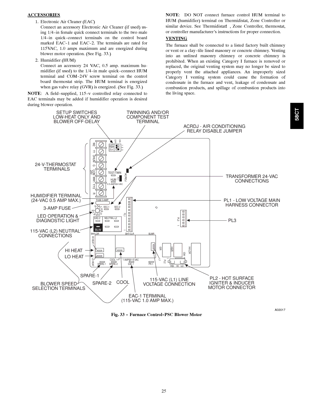
Fig. 33 - Furnace Control-PSC Blower Motor
25