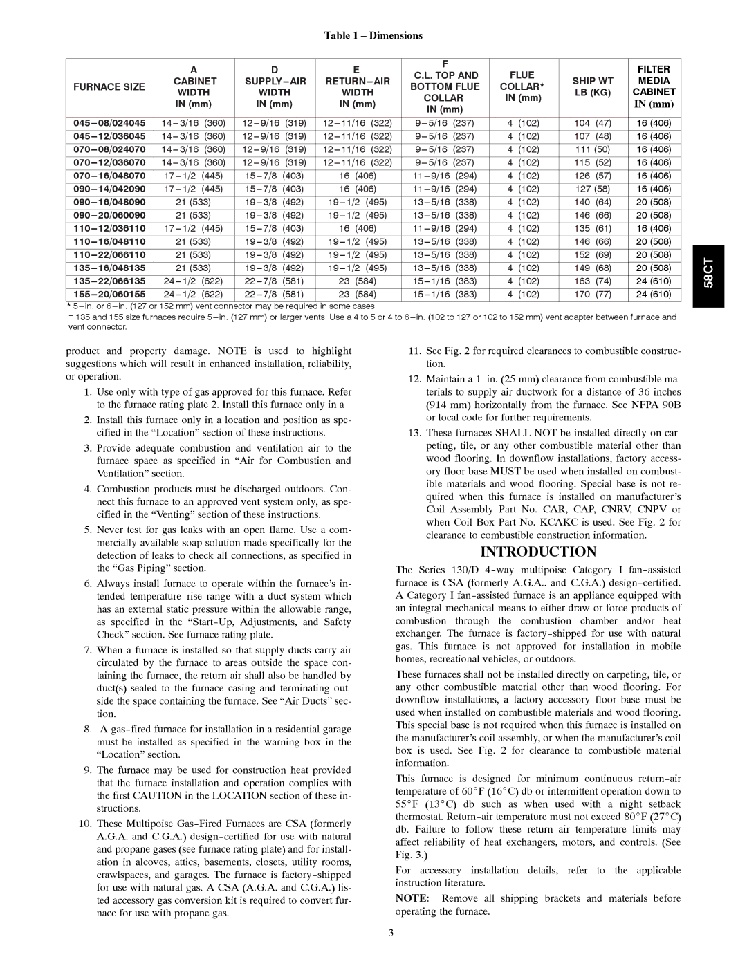
Table 1 – Dimensions
|
|
| A |
|
| D |
|
|
| E |
|
|
| F |
| FLUE |
|
| FILTER | |
|
|
|
|
|
|
|
|
|
| C.L. TOP AND |
|
| ||||||||
|
| CABINET | SUPPLY | RETURN AIR |
| SHIP WT | MEDIA | |||||||||||||
FURNACE SIZE |
| BOTTOM FLUE | COLLAR* | |||||||||||||||||
| WIDTH |
| WIDTH |
| WIDTH |
| LB (KG) | CABINET | ||||||||||||
|
|
|
|
|
|
| COLLAR | IN (mm) | ||||||||||||
|
|
| IN (mm) |
| IN (mm) |
| IN (mm) |
|
|
|
| IN (mm) | ||||||||
|
|
|
|
|
|
| IN (mm) |
|
|
|
| |||||||||
|
|
|
|
|
|
|
|
|
|
|
|
|
|
|
|
|
|
| ||
|
|
|
|
|
|
|
|
|
|
|
|
|
|
|
|
|
|
|
| |
08/024045 | 3/16 | (360) | 9/16 | (319) | 11/16 | (322) |
| 5/16 | (237) | 4 | (102) | 104 | (47) | 16 (406) | ||||||
12/036045 | 3/16 | (360) | 9/16 | (319) | 11/16 | (322) |
| 5/16 | (237) | 4 | (102) | 107 | (48) | 16 (406) | ||||||
08/024070 | 3/16 | (360) | 9/16 | (319) | 11/16 | (322) |
| 5/16 | (237) | 4 | (102) | 111 (50) | 16 (406) | |||||||
12/036070 | 3/16 | (360) | 9/16 | (319) | 11/16 | (322) |
| 5/16 | (237) | 4 | (102) | 115 | (52) | 16 (406) | ||||||
16/048070 | 17 | (445) | 15 | (403) |
| 16 | (406) |
| 11 | (294) | 4 | (102) | 126 | (57) | 16 (406) | |||||
14/042090 | 17 | (445) | 15 | (403) |
| 16 | (406) |
| 11 | (294) | 4 | (102) | 127 (58) | 16 (406) | ||||||
16/048090 |
| 21 (533) | 19 | (492) | 19 | (495) |
| 13 | (338) | 4 | (102) | 140 | (64) | 20 (508) | ||||||
20/060090 |
| 21 (533) | 19 | (492) | 19 | (495) |
| 13 | (338) | 4 | (102) | 146 | (66) | 20 (508) | ||||||
12/036110 | 17 | (445) | 15 | (403) |
| 16 | (406) |
| 11 | (294) | 4 | (102) | 135 | (61) | 16 (406) | |||||
16/048110 |
| 21 (533) | 19 | (492) | 19 | (495) |
| 13 | (338) | 4 | (102) | 146 | (66) | 20 (508) | ||||||
22/066110 |
| 21 (533) | 19 | (492) | 19 | (495) |
| 13 | (338) | 4 | (102) | 152 | (69) | 20 (508) | ||||||
16/048135 |
| 21 (533) | 19 | (492) | 19 | (495) |
| 13 | (338) | 4 | (102) | 149 | (68) | 20 (508) | ||||||
22/066135 | 24 | (622) | 22 | (581) |
| 23 | (584) |
| 15 | (383) | 4 | (102) | 163 | (74) | 24 (610) | |||||
20/060155 | 24 | (622) | 22 | (581) |
| 23 | (584) |
| 15 | (383) | 4 | (102) | 170 | (77) | 24 (610) | |||||
* |
|
|
|
|
|
|
|
| ||||||||||||
{ 135 and 155 size furnaces require 5 in. (127 mm) or larger vents. Use a 4 to 5 or 4 to | ||||||||||||||||||||
vent connector. |
|
|
|
|
|
|
|
|
|
|
|
|
|
|
|
|
|
|
| |
58CT
product and property damage. NOTE is used to highlight suggestions which will result in enhanced installation, reliability, or operation.
1.Use only with type of gas approved for this furnace. Refer to the furnace rating plate 2. Install this furnace only in a
2.Install this furnace only in a location and position as spe- cified in the “Location” section of these instructions.
3.Provide adequate combustion and ventilation air to the furnace space as specified in “Air for Combustion and Ventilation” section.
4.Combustion products must be discharged outdoors. Con- nect this furnace to an approved vent system only, as spe- cified in the “Venting” section of these instructions.
5.Never test for gas leaks with an open flame. Use a com- mercially available soap solution made specifically for the detection of leaks to check all connections, as specified in the “Gas Piping” section.
6.Always install furnace to operate within the furnace’s in- tended
7.When a furnace is installed so that supply ducts carry air circulated by the furnace to areas outside the space con- taining the furnace, the return air shall also be handled by duct(s) sealed to the furnace casing and terminating out- side the space containing the furnace. See “Air Ducts” sec- tion.
8.A
9.The furnace may be used for construction heat provided that the furnace installation and operation complies with the first CAUTION in the LOCATION section of these in- structions.
10.These Multipoise
11.See Fig. 2 for required clearances to combustible construc- tion.
12.Maintain a
13.These furnaces SHALL NOT be installed directly on car- peting, tile, or any other combustible material other than wood flooring. In downflow installations, factory access- ory floor base MUST be used when installed on combust- ible materials and wood flooring. Special base is not re- quired when this furnace is installed on manufacturer’s Coil Assembly Part No. CAR, CAP, CNRV, CNPV or when Coil Box Part No. KCAKC is used. See Fig. 2 for clearance to combustible construction information.
INTRODUCTION
The Series 130/D
These furnaces shall not be installed directly on carpeting, tile, or any other combustible material other than wood flooring. For downflow installations, a factory accessory floor base must be used when installed on combustible materials and wood flooring. This special base is not required when this furnace is installed on the manufacturer’s coil assembly, or when the manufacturer’s coil box is used. See Fig. 2 for clearance to combustible material information.
This furnace is designed for minimum continuous
For accessory installation details, refer to the applicable instruction literature.
NOTE: Remove all shipping brackets and materials before operating the furnace.
3