58CT
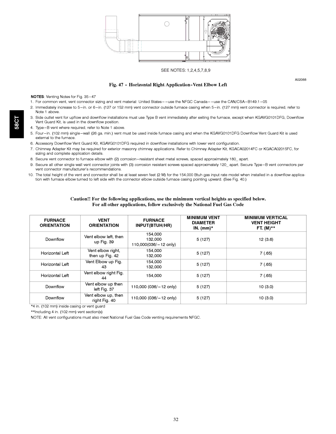
SEE NOTES: 1,2,4,5,7,8,9
A02068
Fig. 47 - Horizontal Right Application-Vent Elbow Left
NOTES: Venting Notes for Fig.
1.For common vent, vent connector sizing and vent material: United
2.Immediately increase to
3.Side outlet vent for upflow and downflow installations must use Type B vent immediately after exiting the furnace, except when KGAVG0101DFG, Downflow Vent Guard Kit, is used in the downflow position.
4.
5.Four
6.Accessory Downflow Vent Guard Kit, KGAVG0101DFG required in downflow installations with lower vent configuration.
7.Chimney Adapter Kit may be required for exterior masonry chimney applications. Refer to Chimney Adapter Kit, KGACA02014FC or KGACA02015FC, for sizing and complete application details.
8.Secure vent connector to furnace elbow with (2) corrosion
9.Secure all other single wall vent connector joints with (3) corrosion resistant screws spaced approximately 120_ apart. Secure
10.The total height of the vent and connector shall be at least seven feet (2 M) for the 154,000 Btuh gas input rate model when installed in a downflow applica- tion with furnace elbow turned to left side with the connector elbow outside furnace casing pointing upward. (See Fig. 40.)
Caution!! For the following applications, use the minimum vertical heights as specified below.
For all other applications, follow exclusively the National Fuel Gas Code
FURNACE | VENT | FURNACE | MINIMUM VENT | MINIMUM VERTICAL | |
DIAMETER | VENT HEIGHT | ||||
ORIENTATION | ORIENTATION | INPUT(BTUH/HR) | |||
IN. (mm)* | FT. (M)** | ||||
|
|
| |||
|
|
|
|
| |
| Vent elbow left, then | 154,000 |
|
| |
Downflow | 132,000 | 5 (127) | 12 (3.6) | ||
up Fig. 39 | |||||
|
|
| |||
|
|
|
| ||
|
|
|
|
| |
Horizontal Left | Vent elbow right, | 154,000 | 5 (127) | 7 (.65) | |
then up Fig. 42 | 132,000 | ||||
|
|
| |||
|
|
|
|
| |
Horizontal Left | Vent Elbow up Fig. | 154,000 | 5 (127) | 7 (.65) | |
43 | 132,000 | ||||
|
|
| |||
|
|
|
|
| |
Horizontal Left | Vent elbow right Fig. | 154,000 | 5 (127) | 7 (.65) | |
44 | |||||
|
|
|
| ||
|
|
|
|
| |
Downflow | Vent elbow up then | 110,000 | 5 (127) | 10 (3.0) | |
left Fig. 37 | |||||
|
|
|
| ||
|
|
|
|
| |
Downflow | Vent elbow up, then | 110,000 | 5 (127) | 10 (3.0) | |
right Fig. 40 | |||||
|
|
|
|
*4 in. (102 mm) inside casing or vent guard **Including 4 in. (102 mm) vent section(s)
NOTE: All vent configurations must also meet National Fuel Gas Code venting requirements NFGC.
32