2.Adjust the gas input rate per the installation instructions. Low gas input rate causes low vent gas temperatures, caus- ing condensation and corrosion in the furnace and/or vent- ing system. Derating is permitted only for altitudes above 2000 ft
3.Adjust the air temperature rise to the midpoint of the rise range or slightly above. Low air temperature rise can cause low vent gas temperature and potential for condensation problems.
4.Set the thermostat heat anticipator or cycle rate to reduce short cycling.
Air for combustion must not be contaminated by halogen compounds which include chlorides, fluorides, bromides, and iodides. These compounds are found in many common home products such as detergent, paint, glue, aerosol spray, bleach, cleaning solvent, salt, and air freshener, and can cause corrosion of furnaces and vents. Avoid using such products in the
Vent dampers on any appliance connected to the common vent can cause condensation and corrosion in the venting system. Do not use vent dampers on appliances common vented with this furnace.
ADDITIONAL VENTING REQUIREMENTS
A 4 in. (102 mm) round vent elbow is supplied with the furnace. A 5 in. or 6 in. (127 or 152 mm) vent connector may be required for some model furnaces. A
See Venting Notes after Fig. 47.
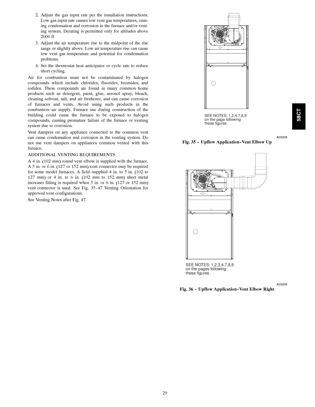
SEE NOTES: 1,2,4,7,8,9 on the page following these figures
A03208
Fig. 35 - Upflow Application-Vent Elbow Up
SEE NOTES: 1,2,3,4,7,8,9 on the pages following these figures
A03209
Fig. 36 - Upflow Application-Vent Elbow Right
58CT
29