Manuals
/
Carrier
/
Household Appliance
/
Furnace
Carrier
58CTA/CTX
instruction manual
A08485
Models:
58CTA/CTX
1
41
56
56
Download
56 pages
38.33 Kb
38
39
40
41
42
43
44
45
Troubleshooting
Install
Chimney Inspection Chart
Wiring
Dimension
Maintenance
Accessories
Start-Up Procedures
Checklist
Cleaning Heat Exchanger
Page 41
Image 41
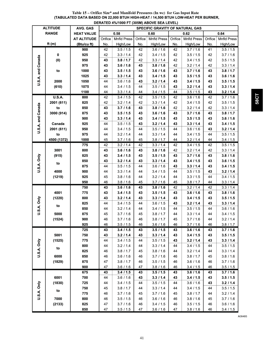
Table 15 – Orifice Size* and Manifold Pressures (In wc) for Gas Input Rate
58CT
A08485
41
Page 40
Page 42
Page 41
Image 41
Page 40
Page 42
Contents
Ama
CUT Hazard
Safety Considerations
Furnace Reliability Hazard
Introduction
Dimensions
Clearances to Combustibles
Codes and Standards
Electrostatic Discharge ESD Precautions Procedure
Carbon Monoxide Poisoning and Unit Damage Hazard
Location
General
Fire Hazard
FIRE, Injury or Death Hazard
Property Damage Hazard
Location Relative to Cooling Equipment
Furnace Corrosion Hazard
AIR for Combustion Ventilation
Carbon Monoxide Poisoning Hazard
Outdoor Combustion Air Method
Air for Combustion, Ventilation, and Dilution for Outdoors
Upflow Installation
Installation
Horizontal Installation
Downflow Installation
FIRE, EXPLOSION, and Carbon Monoxide Poisoning Hazard
Suspended Furnace Support
Roll-Out Protection
Platform Furnace Support
Duct Flanges
Opening dimensions In. mm
Horizontal Unit Suspension
AIR Ducts
Filter Arrangement Carbon Monoxide Poisoning Hazard
General Requirements
Ductwork Acoustical Treatment Supply Air Connections
Speed External Static Pressure IN. WC Size Inlet
Air Delivery CFM With Filter
Furnace
Downflow Furnaces
Air Delivery CFM With Filter*
Return Air Connections
GAS Piping Fire or Explosion Hazard
Upflow Return Air Configurations and Restrictions
Furnace Damage Hazard
Maximum Capacity of Pipe
Electrical Connections Electrical Shock Hazard
Wiring
Electrical Shock and Fire Hazard
Furnace MAY not Operate Hazard
Electrical Connection to J-BOX
Electrical Data
BOX Relocation
BX. Cable Installation in Furnace J-BOX
Power Cord Installation in Furnace J-BOX
Electrical Box on Furnace Casing Side. See Fig
Fire or Electrical Shock Hazard
Two-Stage Furnace with Two-Speed Air Conditioner
See notes 2, 11, and 12 on the page following these figures
Venting
Accessories
Masonry Chimney Requirements
General Venting Requirements
Chimney Inspection Chart
Vent Height
Appliance Application Requirements
Internal Area of Chimney
Upflow Application-Vent Elbow Up
Downflow Application-Vent Elbow Up then Left
Horizontal Left Application Vent Elbow Left
Diameter Vent Height Orientation INPUTBTUH/HR
Furnace Vent
Using Tin Snips to Cut Tie Points
Burn Hazard
START-UP, ADJUSTMENT, and Safety Check
General
Adjustments
Start-Up Procedures
Stage Furnace Setup Switch Description
Fire and Explosion Hazard
Redundant Automatic Gas Control Valve
Altitude Derate Multiplier for U.S.A
Orifice Hole
Seconds Size of Test Dial For Revolution
Gas Rate cu ft. /hr
Furnace Overheating Hazard
Color Speed AS Shipped
Speed Selection
Checklist
Check Safety Controls
Stage Furnace Blower OFF delay Setup Switch
Desired Heating Mode Setup Switch Blower OFF Delay SEC
A08485
Orifice Size and Manifold Pressures In wc for Gas Input Rate
A08219
A08219A
Introduction
Service and Maintenance Procedures
Carbon Monoxide Poisoning and Fire Hazard
Care and Maintenance
Wiring Diagram
Blower Motor and Wheel
Cleaning AND/OR Replacing AIR Filter
Filter Size Information IN. / MM
Unit Damage Hazard
Cleaning Heat Exchanger
Igniter Position-Top View
Sequence of Operation
58CT
Single-Speed Cooling
Single-Stage Thermostat and Two-Speed Cooling Adaptive Mode
Thermidistat Mode
Continuous Blower Mode
Wiring Diagrams
Troubleshooting
Troubleshooting Guide 2-Speed
KitAdapter Chimneyin Usedswitch Shutoffvent Blocked
Catalog No58CT---10SI
Top
Page
Image
Contents