Gas piping must be installed in accordance with national and local codes. Refer to current edition of NFGC in the U.S. and the
Table 6 – Maximum Capacity of Pipe
NOMINAL | INTERNAL |
| LENGTH OF PIPE |
| |||
IRON PIPE |
|
|
|
|
|
| |
DIA. |
|
|
|
|
|
| |
SIZE | 10 |
| 20 | 30 | 40 | 50 | |
IN. (MM) |
| ||||||
IN. (MM) | (3.0) |
| (6.0) | (9.1) | (12.1) | (15.2) | |
|
| ||||||
|
|
|
|
|
|
|
|
1/2 (12.7) | 0.622 | 175 |
| 120 | 97 | 82 | 73 |
(158) |
| ||||||
|
|
|
|
|
|
| |
|
|
|
|
|
|
|
|
3/4 (19.0) | 0.824 | 360 |
| 250 | 200 | 170 | 151 |
(20.9) |
| ||||||
|
|
|
|
|
|
| |
|
|
|
|
|
|
|
|
1( 25.4) | 1.049 | 680 |
| 465 | 375 | 320 | 285 |
(26.6) |
| ||||||
|
|
|
|
|
|
| |
|
|
|
|
|
|
|
|
1.380 | 1400 |
| 950 | 770 | 660 | 580 | |
(31.8) | (35.0) |
| |||||
|
|
|
|
|
| ||
1.610 | 2100 |
| 1460 | 1180 | 990 | 900 | |
(38.1) | (40.9) |
| |||||
|
|
|
|
|
| ||
|
|
|
|
|
|
|
|
*Cubic ft. of natural gas per hr for gas pressures of 0.5 psig
Installations must be made in accordance with all authorities having jurisdiction. If possible, the gas supply line should be a separate line running directly from meter to furnace.
NOTE: In the state of Massachusetts:
1.Gas supply connections MUST be performed by a li- censed plumber or gas fitter.
2.When flexible connectors are used, the maximum length shall not exceed 36 inches (915 mm).
3.When lever handle type manual equipment shutoff valves are used, they shall be
4.The use of copper tubing for gas piping is NOT approved by the state of Massachusetts.
Refer to Table 6 for recommended gas pipe sizing. Risers must be used to connect to furnace and to meter. Support all gas piping with appropriate straps, hangers, etc. Use a minimum of 1 hanger every 6 ft. (1.8 M). Joint compound (pipe dope) should be applied sparingly and only to male threads of joints. Pipe dope must be resistant to the action of propane gas.
!WARNING
FIRE OR EXPLOSION HAZARD
Failure to follow this warning could result in personal injury, death, and/or property damage.
If local codes allow the use of a flexible gas appliance connector, always use a new listed connector. Do not use a connector which has previously served another gas appliance. Black iron pipe shall be installed at the furnace gas control valve and extend a minimum of 2 in. (51 mm) outside the furnace.
!CAUTION
FURNACE DAMAGE HAZARD
Failure to follow this caution may result in furnace damage.
Connect gas pipe to furnace using a backup wrench to avoid damaging gas controls and burner misalignment.
An accessible manual equipment shutoff valve MUST be installed external to furnace casing and within 6 ft. of furnace. A
supply connection to furnace and downstream of manual equipment shutoff valve.
NOTE: The furnace gas control valve inlet pressure tap connection is suitable to use as test gauge connection providing test pressure DOES NOT exceed maximum 0.5 psig
2” (51mm) | 58CT | |
Street Elbow | ||
| ||
| A08551 |
Fig. 21 - Burner and Manifold
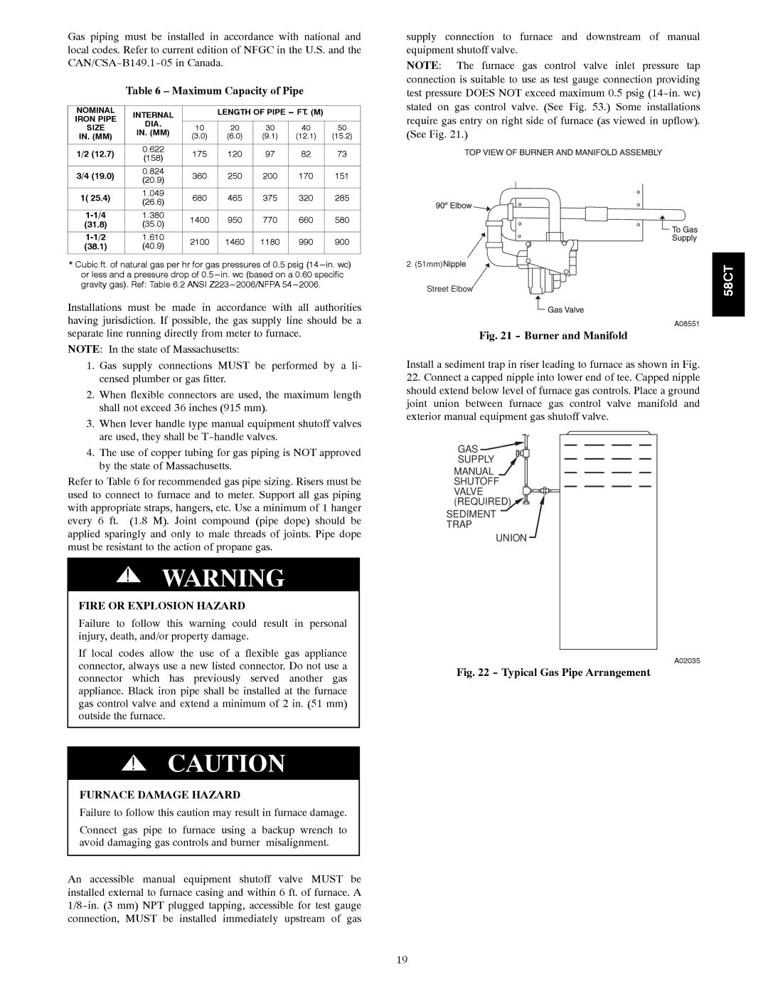
Install a sediment trap in riser leading to furnace as shown in Fig.
22.Connect a capped nipple into lower end of tee. Capped nipple should extend below level of furnace gas controls. Place a ground joint union between furnace gas control valve manifold and exterior manual equipment gas shutoff valve.
GAS![]()
![]()
SUPPLY
MANUAL
SHUTOFF
VALVE ![]()
![]()
![]()
![]() (REQUIRED)
(REQUIRED) ![]()
![]()
![]()
SEDIMENT TRAP
UNION
A02035
Fig. 22 - Typical Gas Pipe Arrangement
19