58CT
A04129 |
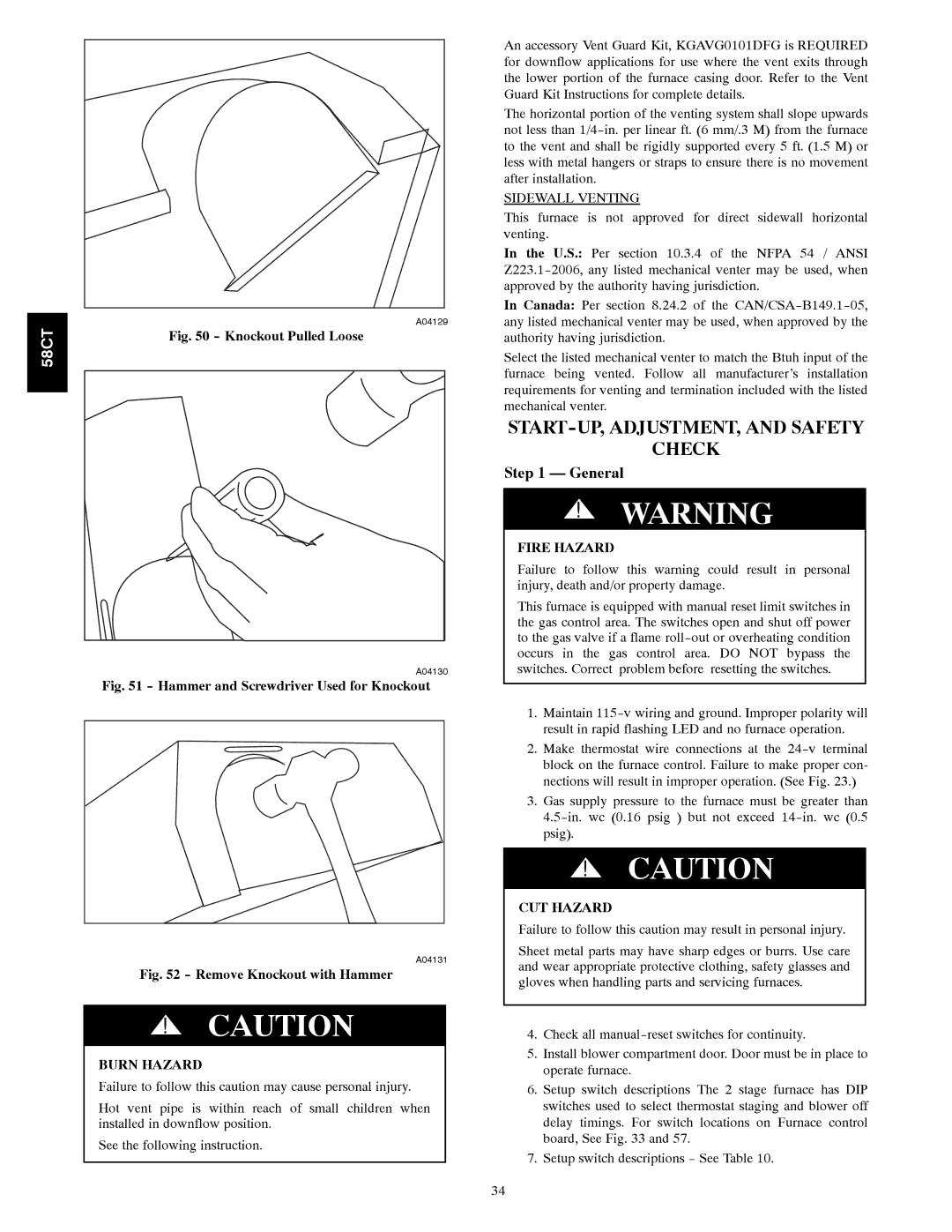
Fig. 50 - Knockout Pulled Loose
A04130 |
Fig. 51 - Hammer and Screwdriver Used for Knockout
A04131 |
Fig. 52 - Remove Knockout with Hammer
!CAUTION
BURN HAZARD
Failure to follow this caution may cause personal injury.
Hot vent pipe is within reach of small children when installed in downflow position.
See the following instruction.
An accessory Vent Guard Kit, KGAVG0101DFG is REQUIRED for downflow applications for use where the vent exits through the lower portion of the furnace casing door. Refer to the Vent Guard Kit Instructions for complete details.
The horizontal portion of the venting system shall slope upwards not less than
SIDEWALL VENTING
This furnace is not approved for direct sidewall horizontal venting.
In the U.S.: Per section 10.3.4 of the NFPA 54 / ANSI
In Canada: Per section 8.24.2 of the
Select the listed mechanical venter to match the Btuh input of the furnace being vented. Follow all manufacturer’s installation requirements for venting and termination included with the listed mechanical venter.
START-UP, ADJUSTMENT, AND SAFETY
CHECK
Step 1 — General
!WARNING
FIRE HAZARD
Failure to follow this warning could result in personal injury, death and/or property damage.
This furnace is equipped with manual reset limit switches in the gas control area. The switches open and shut off power to the gas valve if a flame
1.Maintain
2.Make thermostat wire connections at the
3.Gas supply pressure to the furnace must be greater than
!CAUTION
CUT HAZARD
Failure to follow this caution may result in personal injury.
Sheet metal parts may have sharp edges or burrs. Use care and wear appropriate protective clothing, safety glasses and gloves when handling parts and servicing furnaces.
4.Check all
5.Install blower compartment door. Door must be in place to operate furnace.
6.Setup switch descriptions The 2 stage furnace has DIP switches used to select thermostat staging and blower off delay timings. For switch locations on Furnace control board, See Fig. 33 and 57.
7.Setup switch descriptions - See Table 10.
34