58CT
sea level by an authorized Gas Conversion Station or Dealer. To determine correct input rate for altitude, see example and use 0.90 as derate multiplier factor.
2.Determine the correct orifice and manifold pressure adjust- ment. All models in all positions except Low NOx models in downflow and horizontal positions use Table 15 (22,000 BTUH per burner).
Table 11 – Altitude Derate Multiplier for U.S.A.
ALTITUDE | PERCENT | DERATE MULTIPLIER | |
FT. (M) | OF DERATE | FACTOR* | |
0 | 1.00 | ||
|
| ||
|
|
| |
0.90 | |||
|
| ||
|
|
| |
0.86 | |||
|
| ||
|
|
| |
0.82 | |||
|
| ||
|
|
| |
0.78 | |||
|
| ||
|
|
| |
0.74 | |||
|
| ||
|
|
| |
0.70 | |||
|
| ||
|
|
| |
0.66 | |||
|
| ||
|
|
| |
0.62 | |||
|
|
*Derate multiplier factors are based on midpoint altitude for altitude range.
Low NOx models in downflow or horizontal positions MUST use Table 16 (21,000 BTUH per burner). See input listed on rating plate.
a.Obtain average yearly gas heat value (at installed altitude) from local gas supplier.
b.Obtain average yearly gas specific gravity from local gas supplier.
c.Find installation altitude in Table 15 or 16.
d.Find closest natural gas heat value and specific gravity in Table 15 or 16
e.Follow heat value and specific gravity lines to point of intersection to find orifice size and
f.Check and verify burner orifice size in furnace. NEVER ASSUME ORIFICE SIZE. ALWAYS CHECK AND VERIFY.
g.Replace orifice with correct size, if required by Table 15 or 16. Use only
EXAMPLE 2:
For 22,000 Btuh per burner application, use Table 15. Heating value = 1000 Btuh/cu ft.
Specific gravity = 0.62 Therefore: Orifice No. 43*
Manifold pressure:
*Furnace is shipped with No. 43 orifices. In this example all main burner orifices are the correct size and do not need to be changed to obtain proper input rate.
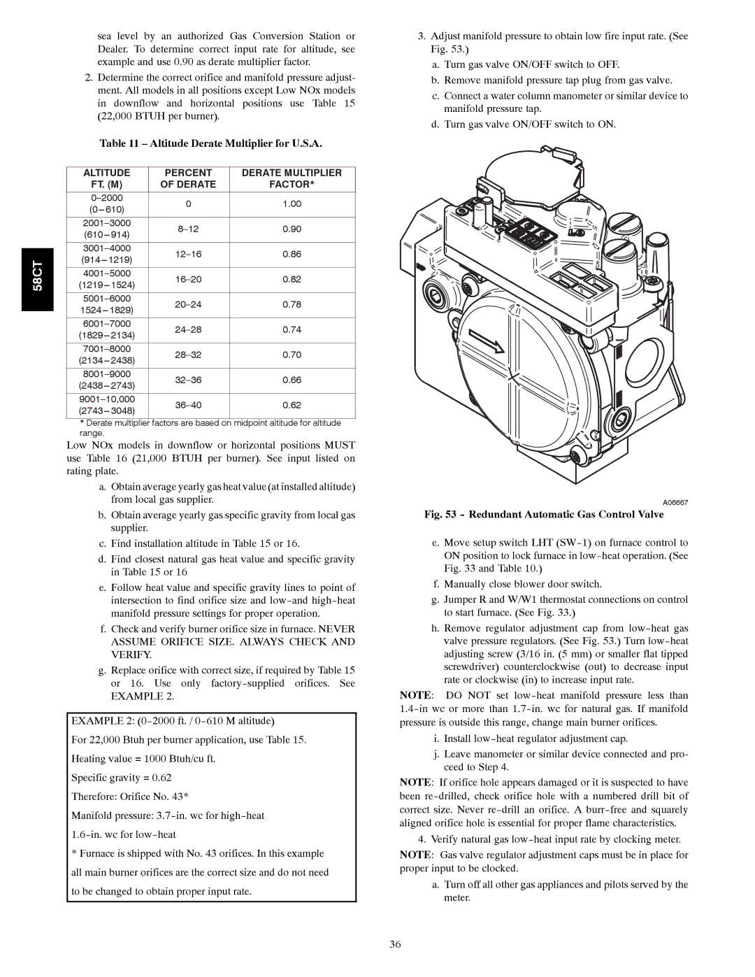
3.Adjust manifold pressure to obtain low fire input rate. (See Fig. 53.)
a.Turn gas valve ON/OFF switch to OFF.
b.Remove manifold pressure tap plug from gas valve.
c.Connect a water column manometer or similar device to manifold pressure tap.
d.Turn gas valve ON/OFF switch to ON.
A06667
Fig. 53 - Redundant Automatic Gas Control Valve
e.Move setup switch LHT
f.Manually close blower door switch.
g.Jumper R and W/W1 thermostat connections on control to start furnace. (See Fig. 33.)
h.Remove regulator adjustment cap from
NOTE: DO NOT set
i.Install
j.Leave manometer or similar device connected and pro- ceed to Step 4.
NOTE: If orifice hole appears damaged or it is suspected to have been
4. Verify natural gas
NOTE: Gas valve regulator adjustment caps must be in place for proper input to be clocked.
a.Turn off all other gas appliances and pilots served by the meter.
36