CONTROL |
| CONTROL |
|
PANEL |
| BOX |
|
2 | 3 |
| 11 |
1 |
| 10 |
|
4 |
|
| |
|
|
| |
| 5 | 9 | 12 |
|
|
| |
| 6 |
|
|
| 7 | 8 |
|
|
|
| 13 |
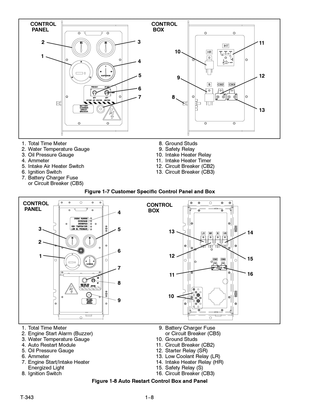
1. | Total Time Meter | 8. | Ground Studs |
2. | Water Temperature Gauge | 9. | Safety Relay |
3. | Oil Pressure Gauge | 10. | Intake Heater Relay |
4. | Ammeter | 11. | Intake Heater Timer |
5. | Intake Air Heater Switch | 12. | Circuit Breaker (CB2) |
6. | Ignition Switch | 13. | Circuit Breaker (CB3) |
7.Battery Charger Fuse or Circuit Breaker (CB5)
Figure 1-7 Customer Specific Control Panel and Box
CONTROL |
| CONTROL |
|
PANEL | 4 | BOX |
|
|
|
| |
3 | 5 | 13 | 14 |
|
| ||
2 |
|
|
|
1 | 6 | 12 |
|
| 15 | ||
|
|
| |
| 7 |
| 16 |
|
| 11 | |
| 8 |
|
|
| 9 | 10 |
|
|
|
|
1. | Total Time Meter | 9. | Battery Charger Fuse |
2. | Engine Start Alarm (Buzzer) |
| or Circuit Breaker (CB5) |
3. | Water Temperature Gauge | 10. | Ground Studs |
4. | Auto Restart Module | 11. | Circuit Breaker (CB2) |
5. | Oil Pressure Gauge | 12. | Starter Relay (SR) |
6. | Ammeter | 13. | Low Coolant Relay (LR) |
7. | Engine Start/Intake Heater | 14. | Intake Heater Relay (HR) |
| Energized Light | 15. | Safety Relay (S) |
8. | Ignition Switch | 16. | Circuit Breaker (CB3) |
| Figure | ||
|
| ||
