4.Run engine 6 to 12 hours and drain system while warm. Rinse system three times after it has cooled down. Refill system with water.
![]() CAUTION
CAUTION
Use only ethylene glycol,
5.Run engine to operating temperature. Drain system again and fill with treated
4.4.6Servicing the Low Coolant Sensor a. Testing the Low Coolant Sensor (LCS)
1. Verify the coolant level is correct.
2. Verify the wiring to the sensor is correct.
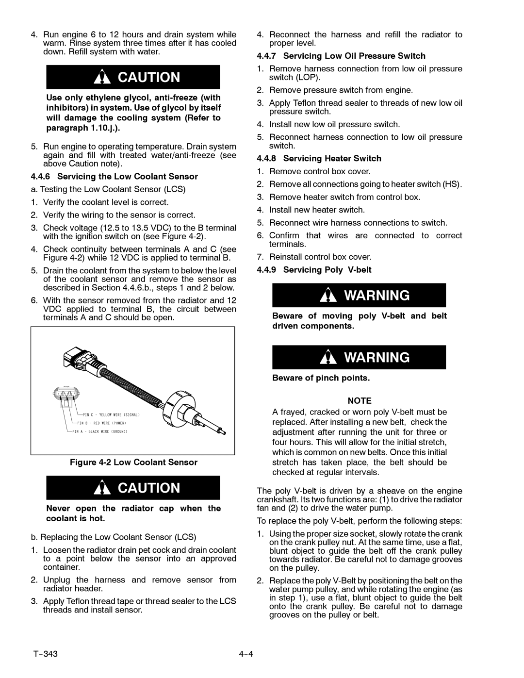
3.Check voltage (12.5 to 13.5 VDC) to the B terminal with the ignition switch on (see Figure
4.Check continuity between terminals A and C (see Figure
5.Drain the coolant from the system to below the level of the coolant sensor and remove the sensor as described in Section 4.4.6.b., steps 1 and 2 below.
6.With the sensor removed from the radiator and 12 VDC applied to terminal B, the circuit between terminals A and C should be open.
4.Reconnect the harness and refill the radiator to proper level.
4.4.7 Servicing Low Oil Pressure Switch
1.Remove harness connection from low oil pressure switch (LOP).
2.Remove pressure switch from engine.
3.Apply Teflon thread sealer to threads of new low oil pressure switch.
4.Install new low oil pressure switch.
5.Reconnect harness connection to low oil pressure switch.
4.4.8Servicing Heater Switch 1. Remove control box cover.
2. Remove all connections going to heater switch (HS).
3. Remove heater switch from control box.
4. Install new heater switch.
5. Reconnect wire harness connections to switch.
6.Confirm that wires are connected to correct terminals.
7.Reinstall control box cover.
4.4.9 Servicing Poly
![]() WARNING
WARNING
Beware of moving poly
Figure 4-2 Low Coolant Sensor
![]() CAUTION
CAUTION
Never open the radiator cap when the coolant is hot.
b. Replacing the Low Coolant Sensor (LCS)
1.Loosen the radiator drain pet cock and drain coolant to a point below the sensor into an approved container.
2.Unplug the harness and remove sensor from radiator header.
3.Apply Teflon thread tape or thread sealer to the LCS threads and install sensor.
![]() WARNING
WARNING
Beware of pinch points.
NOTE
A frayed, cracked or worn poly
The poly
To replace the poly
1.Using the proper size socket, slowly rotate the crank on the crank pulley nut. At the same time, use a flat, blunt object to guide the belt off the crank pulley towards radiator. Be careful not to damage grooves on the pulley.
2.Replace the poly
|