Manuals
/
Carrier
/
Lawn and Garden
/
Portable Generator
Carrier
69UG15
manual
Based On Drawing 62-11413-00 Rev a
Models:
69UG15
1
45
50
50
Download
50 pages
38.25 Kb
42
43
44
45
46
47
48
49
Troubleshooting
Specification
Install
Section Schematics
Wire Ohm
Configuration Identification
Bearing Replacement
Battery Charger
Attempt to Adjust Engine Speed
Outdoor Temperature Centigrade
Page 45
Image 45
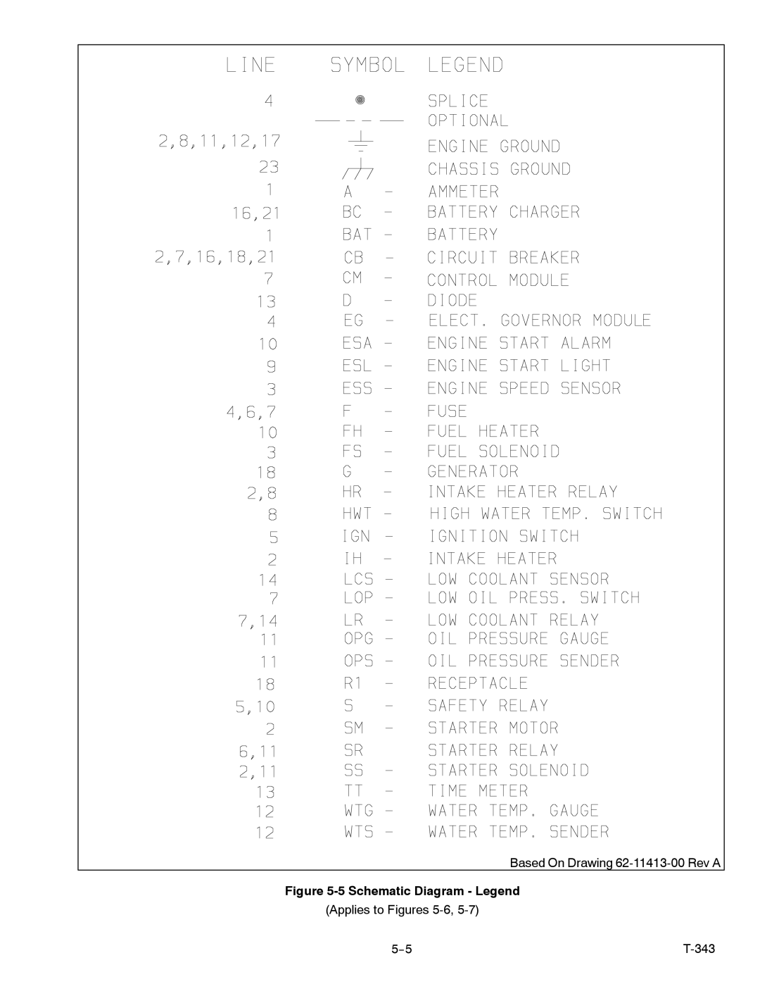
Based On Drawing
62-11413-00
Rev A
Figure
5-5
Schematic Diagram - Legend
(Applies to Figures
5-6,
5-7)
5--5
T-343
Page 44
Page 46
Page 45
Image 45
Page 44
Page 46
Contents
Operation and Service
Model 69UG15
Table of Contents
Table of Contents
List of Illustrations
List of Tables
Table Number
Safety Summary
Specific Warning and Caution Statements
Configuration Identification
Section Description
Introduction
PID
Generator Set
Volt
343
Engine Screw Threads
Engine
Operating Controls and Instruments
Battery Charger
Introduction
Control Panel and Related Components a. Gauges and Senders
Manual Switches
Safety Devices
Meters
Customer Specific Control Panel and Box
Auto Restart Sequencing
Auto Restart Preset Values Indicator Description
Intake Engine Series
Fuel
Auto Restart Sequencing Intake Engine Series
Intake Heater
Unit Specifications
Generator
Nominal Tank Sizes Fill Capacity Draw Capacity
Engine Data
Outdoor Temperature Centigrade
SAE
Winter Summer
Operation
Generator SET Installation
Generator SET Removal
Typical Generator Set Mounting Quick Mount
Cold Engine Preheat Times
Starting and Stopping Instructions
Control Circuit Operation
Remedy
Section Troubleshooting
Condition Possible Cause Reference Section Diesel Engine
Engine Will Not Start
Engine Will Not Shut Off
Condition Possible Cause Reference Section
Starter Motor Malfunction
Malfunction In The Engine Starting Circuit
Battery Charger Solid State
Miscellaneous Engine Troubleshooting
Alternating Current Generator
Auto RE-START Option
Remedy
Section Service and Preventive Maintenance
Preventative Maintenance Schedule
Battery Service
Units
Interval Units Description of Procedure
Every
1000
Hours
Interval Units
Servicing Heater Switch 1. Remove control box cover
Servicing Low Oil Pressure Switch
Attempt to Adjust Engine Speed
Engine Crankcase Breather
Preventative Maintenance and Operating Precautions
Servicing the Alternating Current Generator
Cooling
Winding Insulation Testing
Terminal Strip Cleaning
Wire Ohm
Rotor Damage
Diode Testing
Bearing Replacement
Terminals see Figure
Bolt Isolator
Truss Frame Unidrive
Engine Isolator/Shockmount Replacement
Generator Install Mount With Large Flare AT TOP Frame
Bolt Shockmount
Unidrive Torque Requirements
Engine & Generator SHOCKMOUNTS/ISOLATORS TOP View
Engine Mount Right Side View
Schematic Diagram Legend
Section Schematics
Schematic Diagram
Schematic Diagram 460 Volt Alternating Current Generator
Schematic Diagram 230 Volt Alternating Current Generator
Based On Drawing 62-11413-00 Rev a
Schematic Diagram
Schematic Diagram 460 Volt Alternating Current Generator
Index
Index
Top
Page
Image
Contents